FET Audio F5T Kit
Hi,
has anyone used the F5T V3 Kit from FET Audio? I know he is using a F4 pcb with only 3 pairs of output stages instead of 4. Ok the effect is to have less current and therefore less bass quality? Has this really such a deep impact on the sound quality?
What's your experience with that?
Would appreciate if someone can give a hint!
Cheers,
Mallard
I know he is using a F4 pcb with only 3 pairs of output stages instead of 4
That is more output devices than a F5Tv2, therefore will give lots of bass, current, and power.
I think it would be a wonderful amp!! 😀 😀 😀
I hope so... I bought two sets from him...
Ohh nice, it would be great if you can share your experiences with that!
Unfortunatelly Spencer is out of matched 2SK1530/2SJ201 and it will take till October timframe when he can sell these again.
Unfortunatelly Spencer is out of matched 2SK1530/2SJ201 and it will take till October timframe when he can sell these again.
Look here: enough 2sj201 en 2sk1530 perfectly matched:
http://www.diyaudio.com/forums/swap...s-matched-2sk1530-2sj201-f5-f5-turbo-f5x.html
Walter
my f5t saga
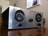
hello all. I have only signed up today. iam looking to make some friends and get help with my f5t build.
my friend riki started to do the electronics on this project for me and I designed and built the chassis. some of you may have seen my amp on here already when he was getting advice on here.
basic issue he blew the amp first time and set fire to it second time lol so we have some issues not sure what though. I will post as many pics as I can to anyone who might be able to help. but so far iam a novice scientific electronic stuff, so go gentle lol.
Attachments
first you need to get som other heatsinks. horisontal fins is a very bad idea for a amp like this🙂
whats the rail voltage and bias? is it with or without diodes. if you have diodes, how are they mounted?
and how many output pairs?
whats the rail voltage and bias? is it with or without diodes. if you have diodes, how are they mounted?
and how many output pairs?
ok so firstly a question I can answer straight away. the heat sinks are fine. they dissipate the heat with no trouble what so ever. I remember asking about that and he said not even at top bias advised for those chips it was cool enough. but I think he reduced the bias.
I need to ask him bout voltage on rails and other stuff as have only just received it back from him. he did build an ordinary f5 which had no trouble but this f5 pushed things a little too far I think as didn't even get to connecting the b1 or the db meters or any of that side of it I think he was using and testing the amp only. and so my suspicion is that it is to do with the wiring inside or the type of wire used or its proximity to the transformer or anything really. as he did say he believes the amp is oscillating and so If I could get an oscilloscope I might find out more.
I have added some more pics of the inside. as far as I know its only one mosfets and diodes burnt out this time last time was the same but only one channel iam not sure this time if more is damaged or if its just same as first time.
what i see here is that the diodes is mounted on the main sink. wich runs so hot that he needed to take the bias down?? the diodes start to conduct earlier when they run hot. so a bias runaway is one possibility. that will blow outputs and set them on fire.
I suggest to avoid this kind of messy solder connections
solid copper wire and solder is very good
but should be done with more care
done like on the bundled resitors seen below may cause too much heat on the components
and could also easily lead to poor connection
which may not even be visible
but in this case it is
solid copper wire and solder is very good
but should be done with more care
done like on the bundled resitors seen below may cause too much heat on the components
and could also easily lead to poor connection
which may not even be visible
but in this case it is
Attachments
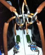
yes. those solder joints will not hold. actualy the whole wireing should be done over.
also. the output boards should be turned around 180 degree. so that the outputs are mounted on the lower half of the sinks.
also. the output boards should be turned around 180 degree. so that the outputs are mounted on the lower half of the sinks.
Last edited:
I remember this amp... I recall the recommendation regarding Teabags PSU boards. There was a hum issue and I think I remember the fact that he smoked something.
Anyways, I agree the wiring is not good. One of the first things my mentor taught me was that the physical connection needs to be good first and then solder. Never use solder to hold the joint together. Granted this was on point to point tube gear, but good advice none the less.
Anyways, I agree the wiring is not good. One of the first things my mentor taught me was that the physical connection needs to be good first and then solder. Never use solder to hold the joint together. Granted this was on point to point tube gear, but good advice none the less.
my friend riki started to do the electronics on this project for me ....
basic issue he blew the amp first time and set fire to it second...
I will post as many pics as I can to anyone who might be able to help. but so far iam a novice scientific electronic stuff, so go gentle lol.
oh ... 😱
rip it apart, and start all over ... learning

Hi Gabsta,
A good start is to remove everything first then PLAN🙂.
Get the appropriate tool. I can even notice wire stripping was not done properly😡😡😡.
Then read the F5 Turbo article and understand it clearly. But would recommend to read the F5 first.
Then look on the build guide of Jim aka 6L6 on F5. There are good pointers there that very much applicable in
building the F5 Turbo especially on the star grounding.... Pay attention to the post of AndrewT on the MAG
and the power ground. Read it word by word and understand what he mean.
Keep in mind, build it one at a time. Do not mix the B1, the VU meter circuit and the F5T in one power-up.
So where to start....build your power supply first and make it sure its working🙂🙂🙂
I don't know what I said, but I did a search and only two posts (2334 & 2336) showed MAG.......................
Then look on the build guide of Jim aka 6L6 on F5. There are good pointers there that very much applicable in building the F5 Turbo especially on the star grounding.... Pay attention to the post of AndrewT on the MAG
and the power ground. Read it word by word and understand what he mean............................
Gabsta,
I don't want to overstate the obvious, but to someone starting out it may not be so obvious. You need to divide and conquer. Don't try to look at everything as a whole at first.
There are a few main parts: Power supply and amp circuit. The F5T is a little more complex in that the amp circuit portion is broken into driver board and output board.
Breaking down the power supply: there is the AC portion, rectification and DC portion.
With no power connected, start looking at the AC side up to the primary side of the transfo- if everything wires like the schema?
After the transformer- look at the rectifiers and how they feed into the capacitor reservoir. Does it match your schema?
With the power supply NOT connected to the amp circuit, with a multimeter, test the voltage of your power supply. Does the voltage match what the expected output voltage of the power supply? If yes, move on to looking at the amp circuit.
You first need to check if all your parts are installed correctly. Check for caps and diodes for correct polarity. Cross-reference their data sheets to be sure. Be sure you understand a schematic symbol versus a physical marking on a part itself.
Be sure you grounded everything properly as well. Can't be overstated. Even if you have everything grounded, it might might not be optimumally grounded. Find info on star grounding and also power vs signal grounding.
If no parts are fryed and you triple checked all wiring, then connected the power supply to the amp circuit. Use a dim bulb tester. If you have a variac, use it and bring up the circuit slowly while watching for the correct voltages and that nothing gets hot or starts to smoke. NEVER TOUCH A LIVE CIRCUIT or a charged circuit with large caps such as this project. Power supply caps must be discharged before working on the circuit every time.
Powering Up Your Radio Safely With a Dim-bulb Tester
Hope this helps,
Vince
Last edited:
I don't know what I said, but I did a search and only two posts (2334 & 2336) showed MAG
I Andrew, The discussion started on post 401. Jim also paste this link on his pp1 on his illustrated build of F5.
Very helpful indeed and many thanks.
My F5T build is very quiet even you put your ear next to the speaker.
- Home
- Amplifiers
- Pass Labs
- F5 Turbo Builders Thread