Hello to all!
So I finally were able to reduce (nearly cancel) my hum.
Big thanks for sharing your story and solving the hum problem in my stereo F5.

I’ve built mine already in 2013, but haven’t found a way to get rid of the slight hum between the inputs until now.

My amp is based on the Diyaudio PCB version 2. Adding HBRL + HBRR to version 2 is even easier than in the case of version 3.
It turned out that I could go to resistor values as low as 0.47 ohms, and the amplifier remains silent.

F5 has been a favourite, and I’m happier with it than ever.

Hello, can someone help please: I keep reading about F5 having wide bandwidth up to 1mhz but can't get mine to show a good sine even at 140khz at full amplitude... it just turns into sawtooth just about over 5volts. Measures well otherwise though.
A more experienced friend suggested it's the highish mosfet capacitance that does this. They are Fairchilds...or so i believe. They do hold 1.4A bias and stable ~0dc at output for quite a while now though...Is it a sign they could be bad/fake etc.?
A more experienced friend suggested it's the highish mosfet capacitance that does this. They are Fairchilds...or so i believe. They do hold 1.4A bias and stable ~0dc at output for quite a while now though...Is it a sign they could be bad/fake etc.?
The frequency response figure has been taken a lower levels, typically
a watt or so. Looks like you are running into slew rate limitations.
Looking at the square wave in the F5 article we see a nice 200 KHz
square wave at 1 watt, and the slew is about 20 V/uS, close to what
the amp will do, depending on the specific parts and other factors.
a watt or so. Looks like you are running into slew rate limitations.
Looking at the square wave in the F5 article we see a nice 200 KHz
square wave at 1 watt, and the slew is about 20 V/uS, close to what
the amp will do, depending on the specific parts and other factors.
Hi everyone,
I recently had an odd power up issue with my F5. Shortly after turning the amp on and while waiting for it to warm up I noticed R8 (F5 v3.0 PCB)was glowing red. I powered it off and checked the value, it no longer reads .47ohms. I’ll have to swap out the resistor but I’d like to find out if another part was the source of the problem. Should I start with checking the Q4 MOSFET? Oddly, the resistor no longer glows when I power it on but I’m not able to get the bias right with the resistor no longer reading .47ohms. Any suggestions on what to look for in searching for the root cause. Thanks.
I recently had an odd power up issue with my F5. Shortly after turning the amp on and while waiting for it to warm up I noticed R8 (F5 v3.0 PCB)was glowing red. I powered it off and checked the value, it no longer reads .47ohms. I’ll have to swap out the resistor but I’d like to find out if another part was the source of the problem. Should I start with checking the Q4 MOSFET? Oddly, the resistor no longer glows when I power it on but I’m not able to get the bias right with the resistor no longer reading .47ohms. Any suggestions on what to look for in searching for the root cause. Thanks.
check mosfets for shorts with diode test , in circuit
when you change 0R47 , power up and rebias
if you can do that , everything is fine
then check for oscillations , if you have scope
if not , try with led thingy for oscillations (attached)
you can increase gate resistors slightly (say 82R to 100R) and you can put caps across feedback resistors
I believe you'll find examples searching for F5 and oscillations ....... but from top of my head .....10n to 15n across R5 and R6
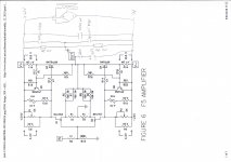
all that referencing schematic shown in Figure 6 , F5-om_sm-080527.pdf
all that , presuming that you didn't use some wimpy resistors in place of 0R47
when you change 0R47 , power up and rebias
if you can do that , everything is fine
then check for oscillations , if you have scope
if not , try with led thingy for oscillations (attached)
you can increase gate resistors slightly (say 82R to 100R) and you can put caps across feedback resistors
I believe you'll find examples searching for F5 and oscillations ....... but from top of my head .....10n to 15n across R5 and R6
all that referencing schematic shown in Figure 6 , F5-om_sm-080527.pdf
all that , presuming that you didn't use some wimpy resistors in place of 0R47
Attachments
Thanks for answers Mr Pass and Zen Mod!
I have a scope and generator and my F5 measures fine to about 50khz - perfect sine, almost perfect square at any (dummy) load or unloaded - no oiscillations, full amplitude, biases well etc.
It just can't hold sine above 5v at high frequencies (140khz+) and i tried to understand if it's natural limitation of the transistors (due to mosfet natural highish capacitance causing a short between P and N at such frequencies) or something is wrong. And if it's normal - can this be improved.
Last edited:
aha .... all those tests are probably culprit of schorched resistor

btw. next time , when asking question which needs somewhat thorough reply , try to include as much details you can - info about pcbs , pictures etc.
when dealing with high bandwidth amps , everything is important
btw. next time , when asking question which needs somewhat thorough reply , try to include as much details you can - info about pcbs , pictures etc.
when dealing with high bandwidth amps , everything is important
Thanks ZenMod. I’ll swap out the resistor, check out / change the MOSFET and bias the amp. Then I’ll check for oscillations. I didn’t Check for oscillations after I completed the original build which is my bad.
Does JFET matching impact the oscillations? I recall I used JFETs from an early batch of LSKs and they may not have been matched very close.
Does JFET matching impact the oscillations? I recall I used JFETs from an early batch of LSKs and they may not have been matched very close.
......
Does JFET matching impact the oscillations?.........
no
if executed properly , price would be only addition of input and output caps, plus few resistors for establishing voltage level of input
why ? thinking of SMPS approach ?
why ? thinking of SMPS approach ?
Yes SMS with single rail.
To avoid input cap it could be possible to use virtual ground with 2 resistors and capacitors...
To avoid input cap it could be possible to use virtual ground with 2 resistors and capacitors...
that's still bipolar supply , but with "artificial" GND
no input and output caps needed
search for Quad supply or Quad GND ...... or look directly in Quad 606 and 909 schematic
covered here already and it works
no input and output caps needed
search for Quad supply or Quad GND ...... or look directly in Quad 606 and 909 schematic
covered here already and it works
I would like to use the artificial ground only to reference the input and feedback loop using 40uf caps and 220r resistors. The output referenced to - V using 4700uf coupling cap. Will this work?
The main psu cap will be single rail not split like quad 606
The main psu cap will be single rail not split like quad 606
Last edited:
It might be better to use an active half-supply with decent current capability, I would look at 500mA as a bare minimum, 1A is better.
The F5 has an unusually large amount of current in the feedback loop and you want the lowest possible impedance you can get. I suspect 220 ohm resistors will drop too much voltage and limit your maximum voltage swing either side of the half-supply mark.
The F5 has an unusually large amount of current in the feedback loop and you want the lowest possible impedance you can get. I suspect 220 ohm resistors will drop too much voltage and limit your maximum voltage swing either side of the half-supply mark.
Good point on the high current feedback.
with two SMPS in series there is always a risk that one powers up before the other, this will send 24V DC to the speaker !
with two SMPS in series there is always a risk that one powers up before the other, this will send 24V DC to the speaker !
- Home
- Amplifiers
- Pass Labs
- F5 power amplifier