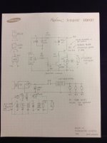
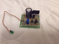
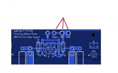
I used the TI LM62 instead which is simpler. I used it to monitor the heatsink temp of my Aleph X and turn on cooling fans to maintain heatsink temp below 50C. I installed the temp sensor chip on a PCB and simply glue the board to the heatsink. I have attached the schematic and the board layout.
I was directed to using thermostats for temperature protection. ........ so in case of overtemperature the amp would turn on and off pretty often.
The thermostat is an admittedly simplistic approach. However, the range of trigger points does allow a selection that provides an adequate margin so activation only happens well above the normal operating range.
I used the TI LM62 instead which is simpler. I used it to monitor the heatsink temp of my Aleph X and turn on cooling fans to maintain heatsink temp below 50C. I installed the temp sensor chip on a PCB and simply glue the board to the heatsink. I have attached the schematic and the board layout.
😀 Your'e the person I've been looking for. 😀 Your design is very encouraging and I'll get in touch with you for more information.
Although KweeSong mentions fans, let me suggest we move the LC discussion over to the Liquid Cooling Thread as to not impose this topic where the focus is properly on the F5 itself.😉
Hi guys, I'm back. Now I've fixed one channel and it's working. The other board is completely disconnected from the psu. No rca connected. I can hear a little hum from the speaker and if I touch the chassis it disappears. Now I stop, waiting for you gurus before going on (as you suggested...)
safety gnd connected to wall ?
audio gnd connected to chassis via NTC?
now , we need again to see pics of wiring .....
audio gnd connected to chassis via NTC?
now , we need again to see pics of wiring .....
psu gnd connected to chassis via NTC.safety gnd connected to wall ?
audio gnd connected to chassis via NTC?
Which is the best point in psu board to connect gnd and ntc?
The hum with no rca connected now is gone moving away from the toroid the wires. But if I connect the rca I have a terrible hum.
I have to correct the scheme in post 14167. I have in my psu board v3:
ST_G1 and ST_G2 shorted
ST_IN1 and ST_IN2 shorted
In some pictures I see all holes are shorted, instead I short only with one wire.
ST_G1 and ST_G2 shorted
ST_IN1 and ST_IN2 shorted
In some pictures I see all holes are shorted, instead I short only with one wire.
Last edited:
You didn't say which grounding paths you are using now (input gnd to amp, or to star on chassis, or everything direct to the PS). "Pictures are worth a thousand words."😉
Did you confirm your interconnects are not shorting internally? Do you have the same hum with a battery powered source such as a Walkman or phone?
Did you confirm your interconnects are not shorting internally? Do you have the same hum with a battery powered source such as a Walkman or phone?
I'm using the original ground scheme in 14167 post.You didn't say which grounding paths you are using now (input gnd to amp, or to star on chassis, or everything direct to the PS). "Pictures are worth a thousand words."😉
Did you confirm your interconnects are not shorting internally? Do you have the same hum with a battery powered source such as a Walkman or phone?
The hum starts as I connect an rca cable, even if it's not connected to a source device. I've tried only phone and notebook as source.
I think next step is manage psu board to short more holes in gnd and stin, to have a lower impedance path. Right?
That really sounds like a shorted interconnect. Did you test it for a short with your meter and/or try other interconnects. You can also disconnect both signal and ground wires at the RCA (or at their termination) - plug the interconnect into the RCA and test again for a short or bleed (continuity) through that path/combo.
You should also try/test the alternate method. Connect the input RCA ground wire to the same spot where you have the PS halves jumpered. That will help you determine if the problem is on the F5 board or somewhere else.
You should also try/test the alternate method. Connect the input RCA ground wire to the same spot where you have the PS halves jumpered. That will help you determine if the problem is on the F5 board or somewhere else.
Last edited:
That really sounds like a shorted interconnect. Did you test it for a short with your meter and/or try other interconnects. You can also disconnect both signal and ground wires at the RCA (or at their termination) - plug the interconnect into the RCA and test again for a short or bleed (continuity) through that path/combo.
You should also try/test the alternate method. Connect the input RCA ground wire to the same spot where you have the PS halves jumpered. That will help you determine if the problem is on the F5 board or somewhere else.
the only short (30 ohm) is between output plugs...
(alternate method) desolder the wire from ingnd in f5 board and connect the wire to psu gnd?
the only short (30 ohm) is between output plugs...
(alternate method) desolder the wire from ingnd in f5 board and connect the wire to psu gnd?
Don't understand what "between output plugs" means. Which points are showing continuity - where are you placing the probes to find that.
Look at the F5 board. There are three pads all on the same trace. They all eventually terminate to the "0" of the +/0/- from the power supply. That allows for flexibility in connecting ground wires. Whether you connect the input ground to the PS or the F5 board you are essentially making the same connection. When I was moving from chip amps to discrete, it was suggested I consider 'ground is ground is ground' as an aid to understanding the circuit.
Attachments
Last edited:
no porn , no joy

Took me a while to learn the ZMese language myself 😀 - but if you don't understand, he is saying PICTURES PLEASE!😉
Last edited:
..... Arrrgh, I can't see through my crystal ball now ....... damn kids , using it for volleyball .......
😉
😉
- Home
- Amplifiers
- Pass Labs
- F5 power amplifier