the transformers secondary are providing two psu = four bridges.
mainaudioground taken after the bridges.
mainaudioground taken after the bridges.
Sorry, what I meant was your gallery shows what appears to be a brown capacitor PCB in the first photo and a red board in others. Not sure it's the same amp.
????????????????
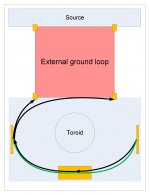
First pic is your design. Note that the grounds and the input cables form a loop around the entire guts of the unit. Connecting the source using two IC's completes that loop.
Second pic shows running one of the input cables, the right in this case, by wrapping it around the ground (green) to the common at the supply board, then the ground to the other channel, then to the left input jack, to the right input jack. Note that this arrangement gets rid of the loop in the power amp chassis. (pardon the crudity of my model)..
Note that you must wrap the external IC's around each other as well.
jn
Attachments

Last edited:
the transformers secondarys go into the prominent wago connectors (grey with orange levers)
and each to left and right into the four rectifier bridges, (the tiny red spots are 3n3caps parallel to the diodes) from there the twisted dc wires pass the transformer thru steel pipes (to avoid hum inducing) and finally reaching the caps board which resides on 2,5cm standoffs. the resistors are placed underneath.
mainaudioground is taken from there and goes to the F5-boards (black wire) and to chassi/earth past two cl-60s.
i suppose replacing the speaker ground from the ampboards to the psu wouldn't make any difference since everything sounds good until i plugin my cd.....
to jneutron,
the (external ground loop) box should be split vertical to fit my design
there are no connections from left to right past the transformer
everything has been kept to its side/channel exept the chassi itself which is separated thru
thermistors.
besides, as i wrote earlier all is fine exept cd input
thanx anyway
....... as i wrote earlier all is fine exept cd input
thanx anyway
I had the exact same problem with two builds. Any source with AC caused a hum - battery power was clean. On the BA-3 the problem was a tiny short/bridge between a power rail/trace and the screw in the standoff nearby. On the other amp it was a combination of a defective RCA socket and poor soldering of the signal-in wires at the PCB. (Actually it was the leads of a two position thru hole screw terminal) In both cases the hum only appeared with both interconnects attached. I do not know why it didn't happen on battery powered sources - but there is no earth/safety ground as with AC
Probably not the case with the F5, but I recently developed a hum on a LM3886 amp that appeared similar. It turned out to be a broken signal wire inside the interconnect RCA plug. I suspect it was shorting/leaking internally. Try a different set of interconnects and inspect the signal leads for possible cold joints. Sometimes a magnifying glass is needed to see bridges and gaps.
Last edited:
to jneutron,
the (external ground loop) box should be split vertical to fit my design
there are no connections from left to right past the transformer
everything has been kept to its side/channel exept the chassi itself which is separated thru
thermistors.
besides, as i wrote earlier all is fine exept cd input
thanx anyway
My drawing was a response to acumos. I do not know what your arrangement is, so am unable to comment.
jn
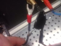
I'm back home. Sorry, hot input-chassis 52kohm, 5 ohm osccillating pem gnd-chassis. In the phot you can see the cl-60 with one lead to pem and chassis, the other lead to psu gnd.260 ohms from signal input to ground means a build error. Remove your signal leads from the RCA jacks and measure hot to ground again. Concur with Sangram if you meant to write output.
If the PEM ground does not go directly to the chassis you misunderstand the build guide. IIRC, Jim used the same place to connect the PEM and signal grounds, but the PEM ground wire goes directly to the chassis.
About the mosfet the resistance to chassis seems growing (cap charging?).
Attachments
Last edited:
There are a few Members referring to:
PEM
Is this something to do with Protective Earth (PE)?
PEM ground ?
What is this?
PEM
Is this something to do with Protective Earth (PE)?
PEM ground ?
What is this?
PEM - Power Entry Module. PEM ground - should probably have said protective earth.
acumos - IF the wire from the PEM protective earth pin is continuous to the chassis lug, OK. If that picture represents a three way soldered connection, it is not OK. Not trying to bust your chops, just trying to make sure it's safe.
acumos - IF the wire from the PEM protective earth pin is continuous to the chassis lug, OK. If that picture represents a three way soldered connection, it is not OK. Not trying to bust your chops, just trying to make sure it's safe.
PEM - Power Entry Module. PEM ground - should probably have said protective earth.
acumos - IF the wire from the PEM protective earth pin is continuous to the chassis lug, OK. If that picture represents a three way soldered connection, it is not OK. Not trying to bust your chops, just trying to make sure it's safe.
No problems with my chops

I've posted a picture about the cl-60, is it ok?
I can't tell from your latest picture, that's why I asked if it is an unbroken wire from PEM to chassis. Did you just strip some insulation back and attach the CL-60?
In the picture you can see a black wire from earth (pem) to a lead of the cl-60 (insulated by tape), a black wire from the same lead to chassis (disconnected to take the photo), a third black wire from the secon lead to psu gnd.I can't tell from your latest picture, that's why I asked if it is an unbroken wire from PEM to chassis. Did you just strip some insulation back and attach the CL-60?
Safer to use a single wire directly from PEM protective earth to the chassis and a completely separate wire from the CL-60 to chassis. Your current solder joint might melt if you have a fault, potentially leaving the chassis hot.
I'm going to follow your suggestion, can this deal with my hum?Safer to use a single wire directly from PEM protective earth to the chassis and a completely separate wire from the CL-60 to chassis. Your current solder joint might melt if you have a fault, potentially leaving the chassis hot.
Possibly. Getting those transformer leads twisted will likely do more.
Check the resistance from PSU ground to the chassis. It should be on the order of 10 ohms. Significantly less and you have an issue such as an input jack that isn't isolated.
Did you resolve the issue of mosfet Drains being shorted to the case? Or was that the 260 ohm reading?
Check the resistance from PSU ground to the chassis. It should be on the order of 10 ohms. Significantly less and you have an issue such as an input jack that isn't isolated.
Did you resolve the issue of mosfet Drains being shorted to the case? Or was that the 260 ohm reading?
- Home
- Amplifiers
- Pass Labs
- F5 power amplifier