> what's wrong with assembling using copper wire, solid core or stranded?
> Too much inductance?
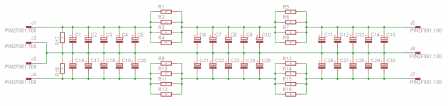
Partly. But partly also that the PCB provides mechanical support to hold the 20 pcs together.
The ripple current in a 100W Class A amp at 8A bias can be easily 40A or higher. Any finite resistance in the connecting wires between the caps will result in unequal current sharing. That is why there are also current balancing resistors (0R1 1W per cap) on the back side of the PCB to make sure of current equalising for the first stage after the rectifiers. For the 2nd & 3rd stage (in CRCRC), the ripple currents are much lower, and one can consider direct connections instead.
Patrick
> Too much inductance?
Partly. But partly also that the PCB provides mechanical support to hold the 20 pcs together.
The ripple current in a 100W Class A amp at 8A bias can be easily 40A or higher. Any finite resistance in the connecting wires between the caps will result in unequal current sharing. That is why there are also current balancing resistors (0R1 1W per cap) on the back side of the PCB to make sure of current equalising for the first stage after the rectifiers. For the 2nd & 3rd stage (in CRCRC), the ripple currents are much lower, and one can consider direct connections instead.
Patrick
Digi-Key - P10335-ND (Manufacturer - EEU-FC1H222)
At 1000 pcs, they cost less than 1 USD per piuece.
Patrick
Yes, but who needs 1000 2200 uF caps? Thats is ALOT of caps.
Say CRCRC per rail, each C 44000uF. Per channel would be 120 caps.
We built in total 8 channels of AXJ-100. So all 1000 caps accounted for.
Patrick
We built in total 8 channels of AXJ-100. So all 1000 caps accounted for.
Patrick
Thinking about PSU size for dual mono F5, what can and cant you do.
I was thinking going for less total capacity but instead focusing on ripple current and low ESR.
NP is using 2 x 15mF/25V Pana TS-UP as 1st cap in his stereo PS. Each one is rated for 4.63A@120Hz, in total >9A.
Not that much for 2.6 DC A continiously drawn. Nonetheless any cap (or bank of caps) exceeding this data should be ok.
Do some simulation or measurement to find out how high the ripple current is.
The standard F5 has relatively low bias at 1,3A, so you can get away with something like 5A ripple spec.
For the F5X, you would need at least double. The result of tight margin on ripple current is reduced cap lifetime.
All engineering compromises.
Patrick
The standard F5 has relatively low bias at 1,3A, so you can get away with something like 5A ripple spec.
For the F5X, you would need at least double. The result of tight margin on ripple current is reduced cap lifetime.
All engineering compromises.
Patrick
I understand Patrck, you're absolutely right, but we were talking about a std F5, werent' we?
I consider 5A as absolute min. anyway.
I consider 5A as absolute min. anyway.
Last edited:
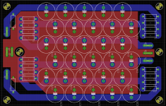
If I build this psu I will be using double layer PCB, with GND on the top layer and the + and - rails on the bottom layer. + in one side and - in the other.
Doing some layout work already, trying to make it as compact as possible. No routing done yet.
Doing some layout work already, trying to make it as compact as possible. No routing done yet.
NP is using 2 x 15mF/25V Pana TS-UP as 1st cap in his stereo PS. Each one is rated for 4.63A@120Hz, in total >9A.
Not that much for 2.6 DC A continiously drawn. Nonetheless any cap (or bank of caps) exceeding this data should be ok.
Correction - TS-HA not TS-UP
Last edited:
Correction - TS-HA not TS-UP

I don't wanna argue, but UP, I'm pretty sure, as long as they are 85° while HA are 105°
Check some hi res 6 moons pics.
Moreover, 15mF/25V UP are 25 (d) x 40 mm, HA 35 (d) x 30 mm.
Max ripple @120Hz: UP 4.63A, HA 3.6A only, a bit too low
I don't mind being wrong. I was certain he used TSHA, I just can't remeber where it was I found that information
ehhh, isnt the UP just a 4-pin snap version of the 2-pin HA ?
I have been looking at those, but cant remember exactly
I have been looking at those, but cant remember exactly
ehhh, isnt the UP just a 4-pin snap version of the 2-pin HA ?
I have been looking at those, but cant remember exactly
That's T-UP (and T-HA), while we were talking about TS-xx series caps.
T-xx style cap has 4 pins for 35 & 40mm diam. and 5 pins for 50mm diam.
ah, yes
TS-UP is rated a lower heat, hence also better current rating
this looks like anice one, and affordable Digi-Key - P6924-ND (Manufacturer - ECO-S1VP333EA)
but if ypou want the real stuff in terms of exstreme long life at high heat ratings, its screw caps
look at can size
I have found 35 x 80mm to be a favourable size
but Im sure snap-in's will last very long too
how hot do they really get
Im sure that good current ratings will keep them cooler
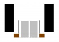
btw, Im planning to mount my caps inside a convection "cooling tower"
"cooling tower" is open at the bottom
fresh air from outside will flow past the caps
this way I hope to keep most of the hot air away from the caps
TS-UP is rated a lower heat, hence also better current rating
this looks like anice one, and affordable Digi-Key - P6924-ND (Manufacturer - ECO-S1VP333EA)
but if ypou want the real stuff in terms of exstreme long life at high heat ratings, its screw caps
look at can size
I have found 35 x 80mm to be a favourable size
but Im sure snap-in's will last very long too
how hot do they really get
Im sure that good current ratings will keep them cooler
btw, Im planning to mount my caps inside a convection "cooling tower"
"cooling tower" is open at the bottom
fresh air from outside will flow past the caps
this way I hope to keep most of the hot air away from the caps
Attachments
btw, this might be worth reading http://www.irf.com/technical-info/appnotes/mosfet.pdf
trying to find a "simple" explanation of forward tranconductance, if there is one
trying to find a "simple" explanation of forward tranconductance, if there is one
Change in Iout/Vin. Example; 1Volt Change at the gate producing a 2A swing at the drain is a gm of 2.
Transconductance - Wikipedia, the free encyclopedia
Transconductance - Wikipedia, the free encyclopedia
ah, it defines current drive gain
I suppose transconductance of N and P channel should be close to equal
and 5 to 10 would be optimal, I guess
I suppose transconductance of N and P channel should be close to equal
and 5 to 10 would be optimal, I guess
what values in the R are optimal.
R increases power supply impedance, you want to keep R low.
R decreases ripple on rails, so you want R high.
Choosing R needs a little experience as you should know what ripple on rails is acceptable for you and that also depends on the amp (PSRR), your speakers (high efficiency...), your listening habits and what not.
In the end, there's so many caps, your supply would also do great without R. However, startup current is massive then, so use something like 0.1-0.47 R.
Have fun, Hannes
The R also has a relationship with the Xl and ESR of the Capacitors. If they are very low you can get away with a smaller R. I ussually have .1-.25 ohm 50W in my supplies.
- Home
- Amplifiers
- Pass Labs
- F5 power amplifier