is 60 x 10^-6 F the same as 60mF?it's pretty impossible that someone is so stupid to think about 60 x 10^-6 F in A class amp PSU
What is wrong with 60mF in high current amplifier?
I know that you know
everyone know that you know ;
but - it was obvious that man does his homework and that using 1x10^-9F instead 1x10^-6F was a typo
all I said is that you're sometimes too serious ; not that you aren't right .
fact , not judging .
everyone know that you know ;
but - it was obvious that man does his homework and that using 1x10^-9F instead 1x10^-6F was a typo
all I said is that you're sometimes too serious ; not that you aren't right .
fact , not judging .
pretty impossible that someone is so stupid to think
Ever tell you about the time i could get my hands on redundant submarine battery cells (2.75V max) by the cheap ?
60mF = 60,000uF = 60,000,000nF
Wups, typo... Good catch!
So are there any issues with powering the "push" and "pull" boards of one channel of the FX5 with separate power supplies?
Ever tell you about the time i could get my hands on redundant submarine battery cells (2.75V max) by the cheap ?
well - it's already pretty well known how great and far are horizons of ZM's and Jacco's stupidity .......
so - that's just outa competition

Wups, typo... Good catch!
So are there any issues with powering the "push" and "pull" boards of one channel of the FX5 with separate power supplies?
it's better to tie them right after Graetz's ;
so - separate Graetz's , common C banks
Even better, power the two amps with a single supply (not symetrical) as there is no return from speaker to ground.
And make a middle voltage point with two resistors for the input ground.
http://www.diyaudio.com/forums/pass-labs/172770-balanced-f5-question-2.html#post2334362
post 13 and following.
And make a middle voltage point with two resistors for the input ground.
http://www.diyaudio.com/forums/pass-labs/172770-balanced-f5-question-2.html#post2334362
post 13 and following.
that's not better ;
just another solution , which will show every imbalance in system .
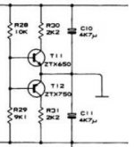
in case that I must do that way , I'll choose ballancing single supply with two bjt network , as Quad does in their 306 and upward models
just another solution , which will show every imbalance in system .
in case that I must do that way , I'll choose ballancing single supply with two bjt network , as Quad does in their 306 and upward models
But there is very little current into the input ground.
The purpose is to settle the input voltage only.
The Quad solution has to deal with return speaker current.😕
The purpose is to settle the input voltage only.
The Quad solution has to deal with return speaker current.😕
Last edited:
But there is very little current into the input ground.
The purpose is to settle the input voltage only.
The Quad solution has to deal with return speaker current.😕
nope ;
same problem ; take a look again at 306 schematic .
frankly - "artificial" gnd can have some virtues , but they're diminishing if you are using "dedicated Graetz for each leg" approach .
in case of "artificial" ground , total symmetry is must
I checked.
The Quad 306 is not a balanced amp and speaker return is to virtual ground.
Our case is different here.
We only need to state the input voltage commonly for the two legs..
Why dedicated graetz?
It is the game in a balanced amp to match everything, or no?
The Quad 306 is not a balanced amp and speaker return is to virtual ground.
Our case is different here.
We only need to state the input voltage commonly for the two legs..
Why dedicated graetz?
It is the game in a balanced amp to match everything, or no?
Last edited:
I checked.
quad 306 is not a balanced amp and speaker return is to virtual ground.
Our case is different here.
We only need to state the input voltage.
It is the game in a balanced amp to match everything, or no?
it doesn't matter that 306 isn't balanced ; you have two "middle" points when amp is in idle - one is spk gnd ...... which is artificial ground produced with two bjt net ; but - same as that is virtual gnd , also amp output is virtual gnd , which is conveniently sliding up and down on potential scale , when we apply input signal
anyway - I wrote that things are critical more on academic level ..... where exactly that academic level is rising his ugly head - you can find if you try all these solutions
if you are enough precise in amplifier execution , you'll not have problems , whichever path you choose ;
point is - I'll sleep tighter , having firm gnd for every needed duty in an amp .
in any case - try and decide what's better / easier for you ....... we are chatting here with best intention , trying to see every piece of puzzle

edit:
Papa made best observation lately - why is wise to use two Graetz/ dedicated windings or each PSU leg ; that way there is no way to have any superposed AC imbalance between windings in xformer , which will result in hum/buzz/whatever ; so - tying upper negative and lower positive ( at Graetzs) is cleanest way to form middle PSU point
Last edited:
🙂 yes i said "better" too fastly.
May be I just want it to be better because it suits to the xformers that lay in my drawers.
Edit: can't use twin graetz with single supply.
May be I just want it to be better because it suits to the xformers that lay in my drawers.
Edit: can't use twin graetz with single supply.
Last edited:
Hi Z.M.
I have been thinking to this last night.
You are right about , in my case, having to use the Quad active virtual ground.
I was forgetting the (low Z) feedabck current flowing to ground.
I will though add two diodes to cancel the dead zone corresponding to the two base emmitor junctions.
Thanks to have pointed that.
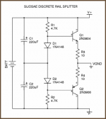
Needs resistors in each collector for current limiting.
I picked up this shematic too fast. Once again.
I picked up this shematic too fast. Once again.
Last edited:
- Home
- Amplifiers
- Pass Labs
- F5 power amplifier