I'm thinking with the Antek 20v secondaries, that it will come out about a volt over the target voltage. That shouldn't be a problem. The Plitron 18v transformer probably runs a bit higher, and you'll get 24v rails like in the genuine F5.
I´ve been surfing around on the different forums of diyaudio.com for a while trying to figure out if anyone can supply prints for an F5-amp project, but with no luck. I have chassis, heatsinks, rectifiers, caps, connectors and switches ready only lacking a transformer, so if someone has a tip for F5 prints that would be nice.
I´ve been surfing around on the different forums of diyaudio.com for a while trying to figure out if anyone can supply prints for an F5-amp project, but with no luck. I have chassis, heatsinks, rectifiers, caps, connectors and switches ready only lacking a transformer, so if someone has a tip for F5 prints that would be nice.
In the Group Buy you have a guy that selling F5 pcb
http://www.diyaudio.com/forums/group-buys/172257-reissue-f3-f5-pcbs-group-buy.html
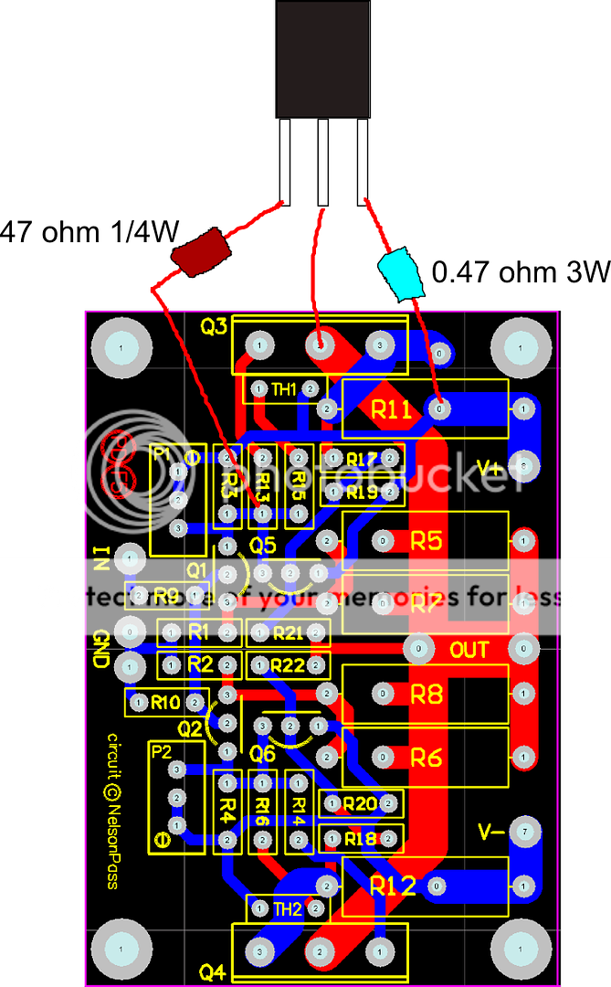
This is my compact F5 layout version, with some differences: no over-current protection (so it's not for people who tend to short-circuit amp's output), 3 x 150R/2W in GNFB network instead of 2 x 100R/3W (I have a large bag of 2 watt-ers).
After a HD crash I lost SprinLayout file, the .gif is all I have. It's a simple layout and can be easily reproduced in any PCB drawing software. It's copper side view, PCB size is 100 x 20 mm. TH1 and TH2 are 4k7 NTC resistors.
After a HD crash I lost SprinLayout file, the .gif is all I have. It's a simple layout and can be easily reproduced in any PCB drawing software. It's copper side view, PCB size is 100 x 20 mm. TH1 and TH2 are 4k7 NTC resistors.
Attachments
Last edited:
Need help with my F5 dual mosfet version...
the 240 side biased up with both 0.47 ohm resistors matching in mV...the 9240 side will not match. the one on the board reads half the voltage as the one off the board. I am using Peter Daniel's board.
I doublechecked the values of the source resistors and R13 and 14...all are correct.
This is most puzzling.
When I adjust the pot the values stay roughly at a 2:1 ratio.
here is a rough schematic of my thoughts...
and Rookie:
I use layout from the last post from this thread (without capacitors) - works fine:
http://www.diyaudio.com/forums/pass-labs/121228-f5-power-amplifier-72.html
My F5 sounds nice with 2x17VAC trafo - around 20-21.5 V under load.
I use layout from the last post from this thread (without capacitors) - works fine:
http://www.diyaudio.com/forums/pass-labs/121228-f5-power-amplifier-72.html
My F5 sounds nice with 2x17VAC trafo - around 20-21.5 V under load.
...compact F5 layout ...
I found the pic of finished modules:
Attachments

Need help with my F5 dual mosfet version...
the 240 side biased up with both 0.47 ohm resistors matching in mV...the 9240 side will not match. the one on the board reads half the voltage as the one off the board. I am using Peter Daniel's board.
I doublechecked the values of the source resistors and R13 and 14...all are correct.
This is most puzzling.
When I adjust the pot the values stay roughly at a 2:1 ratio.
here is a rough schematic of my thoughts...
The only other thing I can think that would not send both sides wacky is possibly the ZTX on the 9240 side gone bad?
This is my compact F5 layout version, with some differences: no over-current protection (so it's not for people who tend to short-circuit amp's output), 3 x 150R/2W in GNFB network instead of 2 x 100R/3W (I have a large bag of 2 watt-ers).
After a HD crash I lost SprinLayout file, the .gif is all I have. It's a simple layout and can be easily reproduced in any PCB drawing software. It's copper side view, PCB size is 100 x 20 mm. TH1 and TH2 are 4k7 NTC resistors.
They look nice yuma! I have never used pcb - software before and I guess there are lots of things you have to learn before using it successfully. I heard about services like this: http://http://cgi.ebay.com/Low-Cost-2-Layer-PCB-Manufacture-Service-1-5-boards-/230337719273?pt=LH_DefaultDomain_0&hash=item35a132abe9.
To start with, what is a gerber-based pcb file?
I got a transformer from an old preamp. It has an XLR connector hooked up to the secondaries. Between the pins my DMM gives me 25, 25 and 50V, so I guess its a dual secondary/centertapped tranny. It is quite big, 11cm diameter and 5,5 high. Could it be like 300VA or something.
+\-25V is a little high for an F5 project, but these voltages will be less when I put a load on the transformer, right. Is it possible to guess the secondary voltages under load from the "off-load" voltages?
+\-25V is a little high for an F5 project, but these voltages will be less when I put a load on the transformer, right. Is it possible to guess the secondary voltages under load from the "off-load" voltages?
They look nice yuma! I have never used pcb - software before and I guess there are lots of things you have to learn before using it successfully. I heard about services like this: http://http://cgi.ebay.com/Low-Cost-2-Layer-PCB-Manufacture-Service-1-5-boards-/230337719273?pt=LH_DefaultDomain_0&hash=item35a132abe9.
To start with, what is a gerber-based pcb file?
Sprint Layout is feature-rich, easy to use, intuitive to learn and cheap PCB software. I made my first PCB with it in a couple of hours after I installed it.
Gerber is a name for universal PCB-production file format (kind of a PDF for PCBs) widely supported by PCB software industry and PCB manufaturers.
Well,
This has been driving me mad all afternoon. I finally ended up pulling the 9240 out of the board and putting the 2 new 9240's in the channel. Funky enough...all is well. Both ends bias up so all 4 source resistors match.
All I can think is that the new vs old mosfets didnt like each other...especially in the 9240's.
So now for the right channel I have the broken in 9240's...of course now the 244's will misbehave for that side... LOL..
Need help with my F5 dual mosfet version...
the 240 side biased up with both 0.47 ohm resistors matching in mV...the 9240 side will not match. the one on the board reads half the voltage as the one off the board. I am using Peter Daniel's board.
I doublechecked the values of the source resistors and R13 and 14...all are correct.
This is most puzzling.
When I adjust the pot the values stay roughly at a 2:1 ratio.
here is a rough schematic of my thoughts...
I got a transformer from an old preamp. It has an XLR connector hooked up to the secondaries. Between the pins my DMM gives me 25, 25 and 50V, so I guess its a dual secondary/centertapped tranny. It is quite big, 11cm diameter and 5,5 high. Could it be like 300VA or something.
+\-25V is a little high for an F5 project, but these voltages will be less when I put a load on the transformer, right. Is it possible to guess the secondary voltages under load from the "off-load" voltages?
I think (if I remember correctly) the voltage is increased by 1.4 times after rectification. Hence the recommended transformer output at 18V AC after rectification is ~25V DC. Just right at the targeted voltage. 300VA is the recommended minimum.
You could always use some power resistors to bring it down though. Or a shunt to ground, to drain off some voltage. Someone more knowledgeable than I will correct me if I'm wrong about the shunt design.
Use what you have.............It's DIY!
Ron
I think (if I remember correctly) the voltage is increased by 1.4 times after rectification. Hence the recommended transformer output at 18V AC after rectification is ~25V DC. ......
without load
with load of "usual" A class channel it's more in range of 1,2-1.25
Duncan's Amp Pages , download PSU Designer , and you'll know , after some play with proggie
Is there any advantage in matching 9240s & 240s in the F5?
In the stock F5 circuit, I don't think so.
In my opinion for get a very close bias on both and "0" offset, the best is as matched as possible.
- Home
- Amplifiers
- Pass Labs
- F5 power amplifier