Way to go mstr!!
i m very jealouscan i ask to you needless question,where did you buy your eurocard board? from rothelectronic?
Thanks!
I think those boards came from farnell, but I´m not shure because I had them in my drawer for some years, waiting for a project.
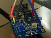
We soldered them up-side-down, just to make sure to have access to all nodes after installation of the board. This technique has proven very practical for first measurements. 🙂
actually you right,this's ideal for measurement.i will do this project ıf i can save money 🙂 but probably i will use peters kits
have a good listen,regards
have a good listen,regards
Patrick (EUVL) and others, can the Balanced F5 be built with 2SK1058/2SJ162 outputs and can they withstand a bias current of 4Amps; or what about the IRFP 240/9240 devices, without thermistors?
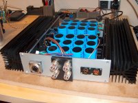
Nice Pics MSTR, your first F5 is much nicer than my first F5.
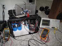
Here's a pic of my first functional channel. It has since evolved into a chassis and grew a brother.
Cool, I really like this sort of engineering!
You are far ahead, the brother of my F5 is still under construction, because after the last update I did some mistake and reversed the PSU polarity at one channel... It´s really a pain to let the smoke out of caddock resistors 🙄
Attachments
I am planning on building a balanced F5. Is your bias 1.6A total for each channel or is that for each pc board ?
As Andrew wrote, it's 1.6A for each pcb I used and therefore 3.2A for each channel.
Uwe
Patrick (EUVL) and others, can the Balanced F5 be built with 2SK1058/2SJ162 outputs and can they withstand a bias current of 4Amps; or what about the IRFP 240/9240 devices, without thermistors?
Hi Sam,
of course you can use IRFP240/9240. But not with a continuous drain current of 4A! If your rail voltages are let's say +/-24V you get a power dissipation of 24V x 4A = 96W for each device. This is too much! The power dissipation for each device should not be higher then 30W.
Uwe
Smyslow, thanks for your reply. So I assume that IRFP240/9240 outputs can be used safely without thermistors. However, I was looking at Patrick's (EUVL) schematic which shows rails of 16 volts and he did mention 4Amps bias with Toshiba devices.
I wonder where the 'sweet spot' lies for each of these device pairs when used in a balanced F5: 2SK1058/2SJ162, IRFP 240/9240?
I wonder where the 'sweet spot' lies for each of these device pairs when used in a balanced F5: 2SK1058/2SJ162, IRFP 240/9240?
What is this thing that DIYr's have w beer?
It's for cleaning away all that blur from soldering smoke.....😀
Smyslow, thanks for your reply. So I assume that IRFP240/9240 outputs can be used safely without thermistors. However, I was looking at Patrick's (EUVL) schematic which shows rails of 16 volts and he did mention 4Amps bias with Toshiba devices.
I wonder where the 'sweet spot' lies for each of these device pairs when used in a balanced F5: 2SK1058/2SJ162, IRFP 240/9240?
You can have 4A bias but you need to parrallel output devices.
4A is too much for a single pair.
Keep the dissipation under 50W per device.
Parallel devices may not be the best for low level sonic resolution. So it is better to keep the bias down to 1.6 amps per side (3.2 amps for balanced F5). But it is so challenging and difficult to decide between the stock F5, balanced F5 and Cascoded F5. Ofcourse one could build all and then decide but I simply don't want to add to all the unused stuff lying in my rented workshop. Simply can't get rid of the ever increasing pile. Plus it will be such a shame to scrap any version of the F5!!
Maybe make one channel point to point.
Try every version, and then choose the one you like best.
Try every version, and then choose the one you like best.
What is this thing that DIYr's have w beer?
... the beer bottles are intended for proper cooling of the output devices, if anything goes wrong 😀
... the beer bottles are intended for proper cooling of the output devices, if anything goes wrong
Or worst case scenario would be to put the fire out.
Just make sure it's not high strength beer otherwise instead of putting out the fire you'll probably burn the house down😀


Hi Mstr,
Thanks for sharing your nice photos and congratulations.
I am intrigued...how the sound compares to the analog rig, left superior corner on the third photo? 😀
Thanks for sharing your nice photos and congratulations.
I am intrigued...how the sound compares to the analog rig, left superior corner on the third photo? 😀
Hi maxlorenz,
well, that´s a little bit difficult to say, because the valve amp needs to be serviced, and I haven´t powered it up since 2007. So blind tests between both are not possible, BUT: even if I cannot do direct comparisons, the F5 is definetly much better, especially at low frequencys (the EL34-Amp lacks a bit auf defined bass) and the most convincing fact is that the F5 has much more resolution and better tracability of the soundstage.
Hard to find the right words in english, but I would say the F5 also has more silence, everything sounds more relaxed, and I dont miss anything in the frequency response of this amp.
So, in short words: after first listening sessions with the F5, I never ever spent a thought about repairing the tube amp. 😎
best regards, Michael
Hello
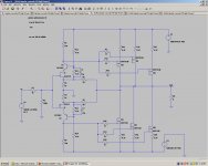
I would like to ask some (help) opinion about a high power F5X with out cascode using multiple power mosfet.
It is possible to use 3pair power mosfet / channel powered from 24V rail power supp. based on the the attached schematic ?
I like these simple schematic (unfortunately it is hard to read any value of the components) any way probably with 24V rail would need adjust most of the resistor values .
In case someone interested for a high power F5X please let me know .
We could make some plan together ,I do not have the skill to modify the schematic to a high power verizon .
I have 14PC 2SK1528 & 18PC 2SJ200 matched Toshiba mosfet , JETs , a 20-0-20VAC 1.5KVA Plitron toroid & monster heat sink (enclosure) over 25lb.
I would like to use these to build a F5X instead a high power F5 .
The (enclosure) heat sink was design for a Aleph2 but I like the X topology better. I have a Aleph X , I like the sound of the X so much , it would be great a high power F5X .
Thank for any advise or help .
Greets
Attachments

If you do the x version you won't really need 3 pairs on each half (2 pairs per half will do), unless of course you want to bias greater than 6A (3A per half).
It is very straight forward to do.
Go for it
Tell us what bias and rail voltage you are intending on using.
The only thing that might be a bit tricky could possbly be adjusting dc offset
It is very straight forward to do.
Go for it
Tell us what bias and rail voltage you are intending on using.
The only thing that might be a bit tricky could possbly be adjusting dc offset
Last edited:
- Home
- Amplifiers
- Pass Labs
- F5 power amplifier