
A question for people who are running higher bias (multiple outputs?).
Are you changing the feedback resistors to get the overall gain back up to 15db? Is that the 'sweet spot'?
Are you changing the feedback resistors to get the overall gain back up to 15db? Is that the 'sweet spot'?
Really not a problem. Just match them up a bit, increase
the Source resistance, and go to town.
Occasionally you will have to think about compensation,
but a cap on the feedback loop resistor will pretty much
take care of it.
😎
the Source resistance, and go to town.
Occasionally you will have to think about compensation,
but a cap on the feedback loop resistor will pretty much
take care of it.
😎

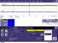
For those that are interested the noise that I get from my switchmode power supply before the RC filter is 7.82 mV pk-pk and after the RC filter is unmeasurable.
The noise floor of the equipment is 1.97 mV pk-pk.
Does anyone know how to do measurements down to microvolts?
I have the equipment, I just don't know if there are any special techniques required to do ultra low noise measurenements.
Anyway I have a picture of the results
The noise floor of the equipment is 1.97 mV pk-pk.
Does anyone know how to do measurements down to microvolts?
I have the equipment, I just don't know if there are any special techniques required to do ultra low noise measurenements.
Anyway I have a picture of the results
Attachments
what amp rating for a on/off power switch do i need using the bog standard F5 PS with thermistors?
@thanh: Assuming 2mV P-P and 0dB PSRR, this would mean (I think) between 0.5 and 12.5 uW (microwatts) into the speakers, at that frequency. Which would be inaudible, I assume. Interesting. Maybe SMPS would be a feasible option for some other builders (I have already purchased my supplies).
90dB/2.8V/m speakers will have 30dB/2.8mV/m2mV P-P and 0dB PSRR,........ into the speakers, ........... Which would be inaudible,
100dB speakers will be 40dB.
Neither of these are inaudible
A 25W amplifier with a 120dB signal to noise ratio will have ~40uVpp of noise at the output. 0.4mVpp would be 100dB signal to noise ratio.
So does anyone know how I can do measurements down to microvolts?
I realy want to know what is the real noise after the rc filter.
I realy want to know what is the real noise after the rc filter.
add a 40dB wideband low noise amplifier between the test equipment and the noise source.
There are a couple of threads on this Forum that describe this technique and they link to web sites that describe the amps in detail.
There are a couple of threads on this Forum that describe this technique and they link to web sites that describe the amps in detail.
Last edited:
I bought some OPA228 as the second best choice for ICs for that amp.
Not built it up yet, so can't report on it's performance.
Not built it up yet, so can't report on it's performance.
At 1m distances, the 40dB could possibly be audible, but the noise floor in my room is 38dB. At listening position, we're talking 24/34dB, well below noise floor except in the dead of the night. And that's at 0dB PSRR, even 10dB of PSRR will knock this well down below the noise threshold of most rooms.
I still think they're not a problem. The F5 notes that
We're talking 1/35th part of 70mV, so I assume it is not a problem at all, and much quieter than a linear supply.
I still think they're not a problem. The F5 notes that
raw supply with two 29,000 uF capacitor and 70 mV ripple will give about 100 uV noise (measured in the band from 20 to 20,000 Hertz).
We're talking 1/35th part of 70mV, so I assume it is not a problem at all, and much quieter than a linear supply.
Does anyone know how to do measurements down to microvolts?
I have the equipment, I just don't know if there are any special techniques required to do ultra low noise measurenements
Linear Technologies has a number of application notes on low noise measurements -- you can search through the archives. Texas Instruments also has an easy to implement design on the product descriptor for the TL431 shunt regulator.
Noise measurement is most relevant when you specify the bandwidth over which it is measured, and the filter topology of the measurement. TI builds a filter in analog for you while Linear uses their switched cap filters. Myself, I prefer CCIR-486 with a 2kHz peak -- but that's beyond the scope of this discussion.
Dennis Colin has an easy to use amplifier using JFET's -- i believe it is archived on the AudioXpress website -- he uses "A" weighting.
We're talking 1/35th part of 70mV, so I assume it is not a problem at all, and much quieter than a linear supply.
Well in reality it might even be 1/100th part of 70mV.
2mV is the noise of the equipment not of the supply. I need to amplify the noise of the supply to be able to measure it.
At this point in time, I only know it is better than 2mV pk-pk.
Maybe SMPS would be a feasible option for some other builders (I have already purchased my supplies).
If someone knows how to mod the voltage of switch mode power supplies then I will start a new thread.
If you search the web I think you will find a lot of people making SMPS of differing voltage / power and some are adjustable within quite wide ranges. It would be better (and in the end possibly cheaper) to buy one fitting your requirements.If someone knows how to mod the voltage of switch mode power supplies then I will start a new thread.
If you can tell me where I can get a 850Watt supply for around $150 with +/-24V rails and with the performance of a computer supply let me know.
Not the right rails, but it's a start:
Connexelectronic
Hypex has a few of them as well. both the creators are active on DIYA, a chat would help figure out how the rails can be modded.
Connexelectronic
Hypex has a few of them as well. both the creators are active on DIYA, a chat would help figure out how the rails can be modded.
- Home
- Amplifiers
- Pass Labs
- F5 power amplifier