My input signal is fine as I use it for another amp of mine. I have a lot of distortion and there is no voltage across R11 and R12, did I do something wrong? Can somebody help?
For now, you have no bias current.
Did you try to proceed to initial adjustment?
Thanks for the reply, and yes, I did adjust P1 and P2, but still can't get any measurement on R11 and R12.
toufu said:Thanks for the reply, and yes, I did adjust P1 and P2, but still can't get any measurement on R11 and R12.
Do you have the P-Channel and N-Channel MOSFETs connected per the schematic?
You have to check again your board and wiring.
Haven't you swapped the jfets?
Be carefull if you power again after a change to put the pots in the initial position otherwise you coud have a too high current.
I suggest you power with a bulb serial connected with mains.
PS: simultaneous with Jackinnj.
Haven't you swapped the jfets?
Be carefull if you power again after a change to put the pots in the initial position otherwise you coud have a too high current.
I suggest you power with a bulb serial connected with mains.
PS: simultaneous with Jackinnj.
Nelson Pass said:
Do you have the serial # of the F5?
Sorry Nelson should have said these were both diy efforts and not one of yours. Perhaps I'm paying the price.
Have measured, as best I know how, no DC off the DAC, and 0.04V at the amps outputs with no signal flowing. This OK?
Thanks
Bvan
the F5 has otherwise been sounding very good - transparent and fast.
f5 mods and bias
Pill
yes I run 1ohm (vs .47 ohm) source resistors at .59 vdc bias at 90 degrees ferinheit
My earlier post was meant to point you at basic trouble shooting as opposed to revising the circuit- the next post after your question pointed you to changing the bias resistors-I think this is a mistake -too many changes making it hard to find the problem-
my f5 runs nicely with the changes that I have noted before following NP's suggested feedback modification and Peter Daniels(and others) suggestions on removing the current limiting(caveat empetor!).
if your power supply is properly wired and your board layout is correct-n channel and p channel devices where they should be, you should be able to raise the bias by fiddling with the 5k ohm pots.
good luck
rob
Re: f5 mods and bias
Hello, after getting completely sidetracked for about a year -- someone once said life is what happens while we are making plans -- I'm finally getting my F5 (and F4, and Pumpy/Shunty) projects going again.
Could some kind soul point toward Mr. Pass' post about feedback modification, and PDs post about current limiting removal? With 170 pages and 4200+ posts (!!) I keep getting lost!
Thanks,
Steve Z
still near Libby, Montana
rob lenk said:Pill
my f5 runs nicely with the changes that I have noted before following NP's suggested feedback modification and Peter Daniels(and others) suggestions on removing the current limiting(caveat empetor!).
rob
Hello, after getting completely sidetracked for about a year -- someone once said life is what happens while we are making plans -- I'm finally getting my F5 (and F4, and Pumpy/Shunty) projects going again.
Could some kind soul point toward Mr. Pass' post about feedback modification, and PDs post about current limiting removal? With 170 pages and 4200+ posts (!!) I keep getting lost!
Thanks,
Steve Z
still near Libby, Montana
Re: f5 mods and bias
There is no worry about increasing slightly R3 & R4, what in fact you did
with the thermistor removal which makes the resultant resistor higer.
rob lenk said:Pill
yes I run 1ohm (vs .47 ohm) source resistors at .59 vdc bias at 90 degrees ferinheit ....
There is no worry about increasing slightly R3 & R4, what in fact you did
with the thermistor removal which makes the resultant resistor higer.
Re: Re: f5 mods and bias
Post 3731 p 150
zettelsm said:
Could some kind soul point toward Mr. Pass' post about feedback modification
Post 3731 p 150
Re: Re: f5 mods and bias
Moreover, just in case you decided to keep the current limiter, mr. Pass suggested to rise R21 and R22 from 10k to 22k
While, if you want to remove it, delete R17, 18, 19, 20, 21 and 22. Then Q5 and 6
zettelsm said:
Could some kind soul point toward Mr. Pass' post about feedback modification, and PDs post about current limiting removal?
Moreover, just in case you decided to keep the current limiter, mr. Pass suggested to rise R21 and R22 from 10k to 22k
While, if you want to remove it, delete R17, 18, 19, 20, 21 and 22. Then Q5 and 6
I checked all my parts and connections, they look fine.. But still, a lot of distortion. I didn't connect the capcitor and themistor on the transformer, would that have made a difference?
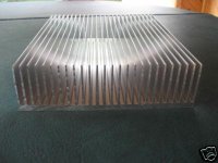
NEW LARGE HEATSINK ON D-BAY
NEW HEATSINK ALUMINUM EXTRUSION LARGE BIG 10.125" WIDE
http://cgi.ebay.com/ws/eBayISAPI.dl...IA&itu=FICS%2BUFI%2BUA%2BIA%2BUCI&otn=4&ps=10
barrredboss
http://shop.ebay.com/merchant/barrredboss
NEW HEATSINK ALUMINUM EXTRUSION LARGE BIG 10.125" WIDE
http://cgi.ebay.com/ws/eBayISAPI.dl...IA&itu=FICS%2BUFI%2BUA%2BIA%2BUCI&otn=4&ps=10
barrredboss
http://shop.ebay.com/merchant/barrredboss
Attachments
heatsinks- o-yea
Ichiban
thanks for finding this listing and offering up for the group
I had seen it a couple of weeks ago but could not find it since
many thanks
rob
Ichiban
thanks for finding this listing and offering up for the group
I had seen it a couple of weeks ago but could not find it since
many thanks
rob
I checked all my parts and connections, they look fine
Could you make some pics?
bvan said:Sorry Nelson should have said these were both diy efforts and not one of yours. Perhaps I'm paying the price.
When asking such questions, it would be helpful if people would
specify. I get more excited if it's one of mine that gives people a
headache.
😎
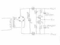
My new (second) F5 is singing on the bench.
As i had no 2x 18v xformer on hand but a 2x36v only, i had to build this PSU which i must say works as well as the normal one.
This is not my idea but inpired from Quad 406 PSU.
I already used it with class AB amps, it is the first class A trial.
As i had no 2x 18v xformer on hand but a 2x36v only, i had to build this PSU which i must say works as well as the normal one.
This is not my idea but inpired from Quad 406 PSU.
I already used it with class AB amps, it is the first class A trial.
Attachments
- Home
- Amplifiers
- Pass Labs
- F5 power amplifier