what type are tr3 ad 4 in the supply ?
ztx652/752 in the 406 schematic. (2A capable)
I used bd139/140 because on hand.
One 10k has to be tweaked in order to get perfect symetry.
I think that second hand 2x 36v transfos are not so rare than 2x18V.
I do not understand.is it "series pass"
This works because average audio signal is 0v, the transistors help to obtain exactly the half voltage. Curiously, with equal resistor values, voltages are not exactly equal. No big currents here. A few kiloohms 2 watts resistors as bleeders should do the job too. but don't ask me too much theory.
This concerns quad 606 ( not 406 sorry) The Quad 909 uses this too and certainly 707 but i am not shure.
Shematics are available with a google search.
bobodioulasso said:
I do not understand.
This works because average audio signal is 0v, the transistors help to obtain exactly the half voltage. Curiously, with equal resistor values, voltages are not exactly equal. No big currents here. A few kiloohms 2 watts resistors as bleeders should do the job too. but don't ask me too much theory.
This concerns quad 606 ( not 406 sorry) The Quad 909 uses this too and certainly 707 but i am not shure.
Shematics are available with a google search.
Your reply answered for me it seems like a virtual earth circuit.
-Dan
I injected 30mv dc at the input and i could see the dc ofset of the speaker . Though this test lasted about 2 seconds. I cannot say if this ofset is not vanishing to zero after a while.
I continue to think the earth is made through the big caps. ( the rails being considered as earth)
But, may be i am wrong.
I continue to think the earth is made through the big caps. ( the rails being considered as earth)
But, may be i am wrong.
This is probably a sign of disconnected amp earth or something like that... the dc offset should dissapear immediately.
unless there is something else in the chain cuaseing this.
-Dan
unless there is something else in the chain cuaseing this.
-Dan
If you put 2 seconds dc at input, you find 2 seconds amplified dc at the output. Where is the problem? May be i was not so clear.
I was saying i did not test dc applied for a long time, that's all.
I have no problem with this amp, just making tests to try to better understand how works this PSU. As you were asking me questions...
I was saying i did not test dc applied for a long time, that's all.
I have no problem with this amp, just making tests to try to better understand how works this PSU. As you were asking me questions...
Dan,
If you inject DC voltage into the input of an F5, you'll always find amplified DC (+ 15dB approx.) at the output, of course. Your amp doesn't care whether the signal is AC or DC.
gm
If you inject DC voltage into the input of an F5, you'll always find amplified DC (+ 15dB approx.) at the output, of course. Your amp doesn't care whether the signal is AC or DC.
gm
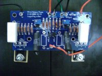
A better picture should be welcome.
Just in case:
The pots are 25 turns. There is to turn several turns before current rises.
IRFP9240 is situated on the positive supply side.
You could unsolder Q5 & Q6 in case they were responsible. The amp works without. (there have been an issue with silkscreen but i do not remember exactly)
Just in case:
The pots are 25 turns. There is to turn several turns before current rises.
IRFP9240 is situated on the positive supply side.
You could unsolder Q5 & Q6 in case they were responsible. The amp works without. (there have been an issue with silkscreen but i do not remember exactly)
toufu said:I built the second channel and still getting the exact same problem, low voltage across R11 and no voltage across R12. I must have connected something wrong. Here is the pic, and thanks for your help.
I would vote for a better picture too...

What is the measured resistance over R3 and R4? Does it change when you turn P1 and P2?
f5 psw with multitorroids
Good morning campers
I'm about to start my second f5 project that will end up being an F5II
meaning four channels paralleled to two. Such fun!
My questions revolve around the power supply. I have on hand four identical 25v dual secondary torroids rated at 160 watts. My thought is to parallel two torroids per side to get to the magical 300va.
Question: best to stack them, lay them side by side, or to arrainge them perpendicular, obviously looking for the least noisy set-up. Also multi pin diode packs like the mur3060 are on paper faster with soft recovery vs the diode bridges- they are also going to coast $50 for the sixteen pieces needed for the Daniel boards vs the $20 for the four bridges.
Opinions please.
In my current set-p I have the rectification and the torroids in a seperate box from the resevoir and the amp modules.No Noise.Yeaha
Question:Of the three pieces in the power supply-
transformer, rectification, and capacitor resevoir, where does the noise come from? My guess is either incoming in on the raw ac, some on the expanding and collapsing magnetic fields around the torroid, the most generated in the rectification and little to none in the cap bank. Am I correct in these assumptions?
inquiring minds wanna know
take care all
rob
I have on hand four identical 25v dual secondary torroids
Hi Frank Zappa.
25V???
four channels paralleled to two
Six channnels?
With its (15db) relatively low gain the F5 is not specially difficult to get silent.
the least noisy set-up
Noise from the mains is the most to fear with toroids (good ones have screens). Depending on where you live.
My 2 F5 are dead silent with no particular precaution. Two transformers and amps in the same box.
Keeping the wires short may help.
Re: f5 psw with multitorroids
Do the same for the other transformer.
It is not advised to parallel separate transformers.
parallel the dual secondaries in one transformer.rob lenk said:My thought is to parallel two toroids per side to get to the magical 300va.
Do the same for the other transformer.
It is not advised to parallel separate transformers.
- Home
- Amplifiers
- Pass Labs
- F5 power amplifier