I am not going to give in on this either.thanh1973 said:Sorry Magura
Andrew was not dead wrong. He was slightly wrong.
If the device to heatsink thermal resistance is correct the sink temperature should be close to case temperature. ClassA with high continuous dissipation (=high heat flow) will give rise to deltaTc-s of ~ 10Cdegrees.
The case temperature must (using Magura's phrase) by definition be higher than the surface temperature of the plastic package.
Read EUVL to understand why.
The clamp bar must also be cooler than the plastic package, even when thermal compound is inserted into the interface.
The clamp bar temperature should be cool in comparison to the case temperature for a correctly mounted ClassA device.
The heatsink should not be cool for a correctly mounted ClassA device, it will be very expensive to keep it cooler than "ouch".
I'll restate what I said.
if the clamping bar is that much hotter than the heatsink then you have a problem. The clamping bar should be cooler than the device case.
Try measuring some real life setups, and you'll see that your theory does not hold true.
It only holds true at lower power levels, but is sure not a linear function.
Try to go to the extreme, and push 100W out of a TO-247 device, then come back when you have a difference of less than 10C between the device case and the heatsink.
Then it will be obvious what's happening.
Magura 🙂
It only holds true at lower power levels, but is sure not a linear function.
Try to go to the extreme, and push 100W out of a TO-247 device, then come back when you have a difference of less than 10C between the device case and the heatsink.
Then it will be obvious what's happening.
Magura 🙂
don't be silly.Magura said:Try to go to the extreme, and push 100W out of a TO-247 device, then come back when you have a difference of less than 10C between the device case and the heatsink.
That implies Rth c-s <0.1C/W.
If you knew anything, you would know that is an impossible target and you would know that asking 100W from a ~150W device leaves no margin to do any work.
Sorry to butt in here guys, but I need your help. I just bought an F3 and F5 to try out (dont have any diy knowledge I should point out) and am liking them both very much. One thing though, I have a suspicion that the F5 is causing me mild headaches of a sort and a strange feeling in my ears. Reading Nelsons warning about voltage bleed and very high frequency occilation I'm wondering if this could be the cause of it?
I've got a centimeter or two between the input cables and the speaker cables but dont know what else I might be wise to do. Thanks very much for any thoughts,
Bvan
I've got a centimeter or two between the input cables and the speaker cables but dont know what else I might be wise to do. Thanks very much for any thoughts,
Bvan
This part of the F5 conversation is entirely derivative -- might I suggest that the moderators take the heat sink portion elsewhere.
bvan said:Sorry to butt in here guys, but I need your help. I just bought an F3 and F5 to try out (dont have any diy knowledge I should point out) and am liking them both very much. One thing though, I have a suspicion that the F5 is causing me mild headaches of a sort and a strange feeling in my ears. Reading Nelsons warning about voltage bleed and very high frequency occilation I'm wondering if this could be the cause of it?
The F5 is particular about cables and grounding as its response goes
out to a megahertz. I would try ordinary speaker cables and regular
well shielded input cables. The stuff you get at Radio Shack would
fill the bill for experimental purposes.
Ordinarily if the amp is oscillating it will run very hot, but if the effect
is marginal or sporadic, that would not be the case.
😎
thanks Nelson. Will experiment with different cables. Amp runs 57C so perhaps a bit hotter than average?
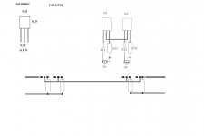
Just started my layout exercise 🙂
Just preliminary to try and get an understanding of what is what
I have a piece of raw board 95x205mm, and cut in two gives me two boards of 45x200mm, and thats what I have to go from
I hope its ok to pop up with this occationally
And would be nice to have errors corrected
Thanks
Just preliminary to try and get an understanding of what is what
I have a piece of raw board 95x205mm, and cut in two gives me two boards of 45x200mm, and thats what I have to go from
I hope its ok to pop up with this occationally
And would be nice to have errors corrected
Thanks
Attachments
post 4192-what are those things?
Hi ya campers-
post 4192 shows some very nice pictures of a first watt product that looks suprisingly like our f5s-
I have a question-
what are the jumpers between thesperate channel power supply boards marked B/C B B/C?
inquiring minds wanna know
tnx
rob
anyone ever find that reference to an e-bay seller selling $45 class A sized heatsinks unanodised?
I built one channel using CViller's board, but I am getting a lot of distortion? 😕
Can somebody help?
Thanks
Can somebody help?
Thanks
Have you checked for DC on the output of the amp? DC on the output of your source or DC on the output of your PreAmp? All these can make things sound terrible but can also kill your speakers.
Uriah
Uriah
bvan said:Sorry to butt in here guys, but I need your help. I just bought an F3 and F5 to try out (dont have any diy knowledge I should point out) and am liking them both very much. One thing though, I have a suspicion that the F5 is causing me mild headaches of a sort and a strange feeling in my ears.
Do you have the serial # of the F5?
Hi Magura
It is not wise to come out and say that someone is dead wrong before you try and understand what has been said.
Next time seek further clarification before criticising.
It is not wise to come out and say that someone is dead wrong before you try and understand what has been said.
Next time seek further clarification before criticising.
Hello there,
i also tried the alternative feedback a´la:
Alternatively, you can increase the value of the Source resistors to 1 ohms, and increase the value of the feedback resistors from 2 X 100 ohms and 10 ohms to 1 X 100 ohms and 22 ohms.
But now i cannot set the bias to more than 1.1A! If i set the dc offset to 0 the bias levels at 0.9A.
Is it correct to increase the value of P1/P2 to 10k?
Is it correct to increase the value of P1/P2 to 10k?
It should be simpler to increase R3 and R4 to 2K7 or 3k3
f5 problem with amp draw
Pill
I had a similar problem at one point in the mod process(ie could not bring the bias up on one channel) and found a cold solder on a ground lead to be the problem.
I am currently(no pun intended) running my f5 with the revised feedback and no current limiting or thermister and have no problems setting bias- I did make sure to set the bias around .4vdc until the amp had warmed up for about an hour then reset to .59vdc and watched and micro tweaked for the next hour.
with my heatsinks and fan arraingment my usual ambient temp directly above the mosfets is about 20 degree ferinheit above room temp.
Hope this helps
rob
- Home
- Amplifiers
- Pass Labs
- F5 power amplifier