...another fet clamp
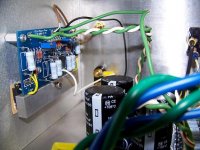
I have the mosfets clamped to the Conrad HS with an aluminum bar. I haven't
yet measured the temp on this bar but it is ripping hot. Heatsink passes the hand test, about six or seven seconds maybe longer, after two hours.
I'm somewhat worried about the fets longevity because of the bars heat.
Bias is set up as per NP.
Attachments
thanh1973 said:If you can hold your fingers for 6 to 7 seconds then you should be fine.
Just to be clear thats 6 to 7 seconds on the heatsinks. I'm concerned about the bar that clamps the fets to the HS. I can put my finger on it for a second.

paulb said:
If
P=RxI^2
Then
I = sqrt(P/R)
Plugging in the 50W example:
I= 3.5355... or 2.5*sqrt(2)
Maybe you could also explain why this is different by a factor of sqrt(2) than your calculation example.
It would also be nice to provide a formula for the required supply rails for a Class A amp for given max power and load impedance. Then we'd be all set. What voltage drop across the output transistors would be reasonable?
It looks like you want to make it more confuse for Tinitus (and some others).
Of course, peak and Rms values have to be taken in account.
Wanting to stay simple:
With 2.5A bias, the pk current is 5A (see post 4143)
5A into 4Ohms produce 5A*5A*4Ohms=100wPk
100wpk = 50w Rms
About 20 volts from the 24 volts rails are available. About 4 volts drop into device + source resistor.
let V this available voltage.
V^2 /R load = P pk.
P=Pk/2
In our example
20*20/4 = 100wpk
=50wRms
While i am there, i made a mistake in post 4143:
The amplitude of the variation is from 0 to 2*bias.
Re: ...another fet clamp
use mica and white goo
ichiban said:I have the mosfets clamped to the Conrad HS with an aluminum bar. I haven't
yet measured the temp on this bar but it is ripping hot. Heatsink passes the hand test, about six or seven seconds maybe longer, after two hours.
I'm somewhat worried about the fets longevity because of the bars heat.
Bias is set up as per NP.
use mica and white goo
Hi,ichiban said:Just to be clear thats 6 to 7 seconds on the heatsinks. I'm concerned about the bar that clamps the fets to the HS. I can put my finger on it for a second.
if the clamping bar is that much hotter than the heatsink then you have a problem.
The clamping bar should be cooler than the device case. I believe that due to the plastic package insulation that the clamping bar should be much cooler than the device case.
There appears to be too much thermal resistance between the device case and the heatsink.
If the thermal resistance is low (correct) then the device case Tc should be within 5 to 10Cdegrees of the heatsink temperature.
What Andrew says makes a lot of sense.
It would be nice if you could measure the temperarure though (possibly with a thermocouple). The bodies response to temperature is not linear. Once you get over 60 degrees celsius the bodies reaction is "this is bloody hot" regardles of whether it is 70 degrees or 100 degrees.
EDIT: I was just having a look at the heatsink surface. It doesn't look to even/smooth from what I can tell in the picture.
Also what are you using between the mosfet and the heatsink?
Is it some sort of tape or silpad?
If the heatsink surface is too rough and the thermal pad too thin then you not going to get good heat transfer.
Ideally you want an ultra smooth and even heatsink surface and a very thin thermal pad, however if the surfaces are rough and uneven a thin thermal pad will not give you good interfacial contact (ie you will have lots of air gaps) and heat transfer will be poor indeed.
What if you put your finger on the heatsink but put your finger about 2cm away from one of the mosfets.
How hot is it here?
Is it similar to the clamp?
The bar clamp could be the problem. Although it looks nice and substantial I bet it's bending at the screw which will keep the fet from sitting flat. Even if it's not visible to the eye, the inside edge of the fet (near the screw) probably has more pressure on it which is causing the outside edge to lift.
It is best to have a screw on both sides of fet for even pressure.
N
It is best to have a screw on both sides of fet for even pressure.
N
Once you sort this issue out. I would like to make one more comment.
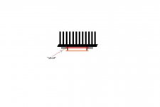
It would be better to have more suface area than thermal mass since you already have a large thermal mass in the heat sink.
By increasing the surface area you are improving your cooling efficiency through convection.
You could achieve this by putting a whole heap of screws into the clamp. Have a look at the image to get an idea. http://www.newegg.com/Product/Product.aspx?Item=N82E16835108037
Or make some fins to attach to the clamp
This is a lot of effort I know, and I would only suggest it if you are really desperate to try and cool things down further
thanh1973 said:
It would be better to have more suface area than thermal mass since you already have a large thermal mass in the heat sink.
By increasing the surface area you are improving your cooling efficiency through convection.
To increase thermal surface to heatsink
You can mount a copper plate between trasistor and heatsink
Copper plate should be as big as layout permits
Transistor and copper plate should have direct contact
This way its possible to use much bigger isolating pads, and have greater thermal contact
Drawbacks
Yet another material between transistor and heatsink
Maybe even greater demands for a 100% smooth surface
Copper plate is electrically active, and a risk of failure if accidentally handled/touched wrongly
The number of drawback makes the benefit questionable
Inspiration comes from ESP site
Anyway, I expect the transistors to always be slightly hotter than heatsink
Thats how the cooling works
If equally hot, I would rate cooling as less effective
Just thoughts🙂
btw, Peter Daniels boards makes it possible to not use isolating pads at all, and mount transistors directly on each their own heatsink
Not sure I would recommend it though, but its possible still
One more thing that can be done is to lap the heatsink surface on a granite surface plate with lapping compound. You could even lap the mosfet but you would be taking a risk of static damage unless the leads were all shorted together. I should mention that this is messy as well as a lot of work . If you are using a copper pate it should be done as well. This can potentially improve the surface contact in major way, but is probably only for the fanatic. Typically a heatsinks surface is not very flat I have even seen some with deep marks from a quick milling operation I have found it neccesary in a few factory made amps to lap the heatsink to prevent the surface roughness from puncturing the insolators😱 A cheaper method for those without a surface plate is to use a cast iron top on a tablesaw and a sheet of silicon carbide wet\dry sandpaper layed on top.
I hope Iam not just muddying the thread here with useless info.
I hope Iam not just muddying the thread here with useless info.
Thermistors
I ordered the amplifier parts for my F5 today except for the thermistors. I'm planning on using the Epcos K45 type thermistors. These have a threaded head that I want to screw into the heatsink near the output MOSFETs. My idea is that warm-up time will be shorter and adjusting bias can be done quicker.
Any thoughts on this approach?
Re: Thermistors
Use thermal compound to exclude air from the threaded joint and from the blind end of the hole.
make sure the threaded portion has no air in the gaps.Beftus said:Epcos K45 type thermistors. These have a threaded head that I want to screw into the heatsink near the output MOSFETs. ................
Any thoughts on this approach?
Use thermal compound to exclude air from the threaded joint and from the blind end of the hole.
amp-guy said:A cheaper method for those without a surface plate is to use a cast iron top on a tablesaw and a sheet of silicon carbide wet\dry sandpaper layed on top.
Affix the silicon carbide paper to the saw top with double-stick tape.
No doubt mounting amp board flat on heatsink is convenient and preferred method
Though I see some heat radiating issues
Significant or not, I have thought of a remedy
Picture shows how I will mount a small sheet of glassfiber "asbest"
Asbest is not used any more, but is mostly made of glassfiber
I have some with alu foil on one side
Glasssfiber is known to cunduct statical electricity, but amp board is glassfiber as well, so I guess its of little concern, but not sure as we are dealing with mosfets, sensitive to that
But once mosfets are soldered I suppose its not an issue
Anyway, this is how it looks
btw, my black plated heatsinks have a white treatment between plating and alu, and Im not sure thats very ideal
It appears that Conrad heatsink have no plating on mounting surface
I consider to order 1meter raw heatsinks with no plating
I expect it to be cheaper as well
Though I have very nice boards from Cviller and PDaniel I consider to play with a layout with an option for a 2 pair transistors, from the scematic nicely shown by "thanh"
Attachments
jackinnj said:
Affix the silicon carbide paper to the saw top with double-stick tape.
the double stick tape is thick enough to disturb the flatness of the surface,
I just wet the backside of the wet\dry paper this causes it to stay in place quite well. Remember to wipe the top dry when finished however or your top will rust.
- Home
- Amplifiers
- Pass Labs
- F5 power amplifier