estman said:I suggest to replace them with jumper and appropriate series resistor.
While there's nothing wrong with doing this, you will find it a tedious
procedure to get it exactly right.
I think that pots get a bad rap. The Bourns pots that I use have not
been a source of problems, and we come back years later and they
are still fine.
😎
Nelson Pass said:
While there's nothing wrong with doing this, you will find it a tedious
procedure to get it exactly right.
I think that pots get a bad rap. The Bourns pots that I use have not
been a source of problems, and we come back years later and they
are still fine.
😎
Hi Mr.Pass,
thanks for useful hint and after all - for this marvelous F5 design to diy community !
Do you have an opinion about adding SF stage to drive more output mosfets ? http://www.diyaudio.com/forums/attachment.php?s=&postid=1655535&stamp=1226405822 (Post2017).
After reading your article "Distortion and Negative Feedback" I have already dropped intention to cascode input jfets for higher supply voltages.
Now I think its just better to get more efficient speakers.
its night in usa and Mr Pass is sleeping now can i help you 😀
i am asking the same question him as same as you.because i have 86db 20cm german WESTRA KW-200-1316 speakers.they have unusual Q parameters ,they need unusual big box volume and they need a bit more power..thanks
i am asking the same question him as same as you.because i have 86db 20cm german WESTRA KW-200-1316 speakers.they have unusual Q parameters ,they need unusual big box volume and they need a bit more power..thanks
Bill Fuss said:Hi thermos,
First thing,if you haven't done it yet, remove the 1k resistors you have in series with the trimmers and jumper those positions. You cant trim down to zero if you have a 1k resistor in the circuit.
With the amp off set your trimmers so you read zero ohms across r3 and r4. Now you can power up. If you have two meters put one across r11 and one from output to ground. If not then just move it back and forth. Start by bringing up the voltage across r11 to around .1v, then watching the meter on the output equalize the circuit by adjusting the other trimmer. If this cannot be done you have to find the problem. If all is OK then bring up r11 to .2v, then equalise, and so on. If you can keep your offset around zero then you know the current is identical through r11 and r12.
That's about it if I didn't forget something. Someone else will chime in, I imagine.
Bill
Thanks Bill for your post.
I followed your advice and was able to get the output to fluctuate around 0-5mV. I would imagine that this is acceptable.
Regards
Thermos
That's a great number. Once you put it in a case, button it up, turn it on and let it cook a while and check the offset. It will drift a little, mine changed about 8-10 mv.
Bill
Bill
another mod
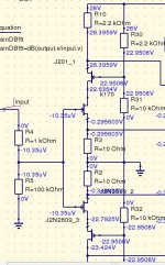
Ok, in my construction I have to 21 AC toroids providing ~28 volt dc. Because of the 25 volt rating of the 2sj74 which I use for input jfets i cascoded them both (2sk170 and 2sj74) with other two matched jfets. The voltage divider for the input of cascoded jfets is 2.2k/10k. Doing this the input jfets are working at around 22 volt so we are OK. Do you think that is better to remove the cascade, is the 28 volts dangerous for the input jfets? By cascoding this way do you thing I am doing anything wrong to the perfomance of F5. In sound I didn't noticed anything different.
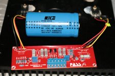
The attached image is showing the case.
Any thoughts are welcome.
Thanks
Ok, in my construction I have to 21 AC toroids providing ~28 volt dc. Because of the 25 volt rating of the 2sj74 which I use for input jfets i cascoded them both (2sk170 and 2sj74) with other two matched jfets. The voltage divider for the input of cascoded jfets is 2.2k/10k. Doing this the input jfets are working at around 22 volt so we are OK. Do you think that is better to remove the cascade, is the 28 volts dangerous for the input jfets? By cascoding this way do you thing I am doing anything wrong to the perfomance of F5. In sound I didn't noticed anything different.
The attached image is showing the case.
Any thoughts are welcome.
Thanks
Attachments
Re: another mod
IMO 28Vdc is still OK because there is voltage drop Vgs of output mosfet (~4V in case of IRFP mosfets) + drop on source resistor.
If you choose to cascode - don't connect biasing resistors to GND.
IMO 28Vdc is still OK because there is voltage drop Vgs of output mosfet (~4V in case of IRFP mosfets) + drop on source resistor.
If you choose to cascode - don't connect biasing resistors to GND.
Re: another mod
cascode them to 10 to 13V
kzeprf22 said:Ok, in my construction I have to 21 AC toroids providing ~28 volt dc. Because of the 25 volt rating of the 2sj74 which I use for input jfets i cascoded them both (2sk170 and 2sj74) with other two matched jfets. The voltage divider for the input of cascoded jfets is 2.2k/10k. Doing this the input jfets are working at around 22 volt so we are OK. Do you think that is better to remove the cascade, is the 28 volts dangerous for the input jfets? By cascoding this way do you thing I am doing anything wrong to the perfomance of F5. In sound I didn't noticed anything different.
The attached image is showing the case.
Any thoughts are welcome.
Thanks
cascode them to 10 to 13V
Re: Re: another mod
Hi thanks again for your advice, where shall I connect the resistors? Floating?
estman said:
If you choose to cascode - don't connect biasing resistors to GND.
Hi thanks again for your advice, where shall I connect the resistors? Floating?
Re: Re: Re: another mod
Yes
😉
kzeprf22 said:
Hi thanks again for your advice, where shall I connect the resistors? Floating?
Yes
😉
Re: Re: another mod
Hi, thanks for the reply. Why particulary 10 to 13 volts. My thought is to have the input jfets biased as high as possible (as in original circuit) due to distortion figures. The cascoded jfets IMO are there just for protection of the input one. And again this My Opinion.
Zen Mod said:
cascode them to 10 to 13V
Hi, thanks for the reply. Why particulary 10 to 13 volts. My thought is to have the input jfets biased as high as possible (as in original circuit) due to distortion figures. The cascoded jfets IMO are there just for protection of the input one. And again this My Opinion.
Thanks, I would like also to see any opinion of Mr Pass, concerning this dilemma i am facing. Should I cascode jfets or 28 volts willl not damage jfets and performance? If I cascade (like the previously attached schematic) what voltage is the optimum? I'll wait a little bit cause I am really confused.
Why not filter the PS with a VBE multiplier?
Noise improves and you get rid of 3.5-4 V down to 24.....
Just add two semi, 4 caps and 4 resistors
Copy Q5, C7 et cetera from the Pearl project and reverse for V-
Noise improves and you get rid of 3.5-4 V down to 24.....
Just add two semi, 4 caps and 4 resistors
Copy Q5, C7 et cetera from the Pearl project and reverse for V-
Both amps initially seem to be working but there is a difference in temp of around 20C between the amps.
The amp that originally had its input JFETs blown (now replaced) stays at around 30C, whilst the one that was working from the start is around 50C. Both amps have the same heatsink and the bias voltage is set the same.
Would I be best changing the MOSFETs of the one that blew the JFETS or any other ideas?
Thanks once again!
Thermos
Hi thermos,
Unless your heatsinks are the size of small refrigerators they should be closer to 50 than 30, but you knew that already. Have you checked both .47 resistors on that channel and rechecked your offset?
Bill
Unless your heatsinks are the size of small refrigerators they should be closer to 50 than 30, but you knew that already. Have you checked both .47 resistors on that channel and rechecked your offset?
Bill
I believe I worked out the problem (I think!) - the amp that was getting hot, when I measured the resistance across R10 (100K) it was only 7.5K Ohms.
When I replaced the JFETS , the resistance across R10 returned to 100K.
Originally I had all JFETS with 7.0 in both amps, now that I have replaced them on the faulty amp with a set that is 8.4, is that likely to make a difference?
Thanks
Thermos
When I replaced the JFETS , the resistance across R10 returned to 100K.
Originally I had all JFETS with 7.0 in both amps, now that I have replaced them on the faulty amp with a set that is 8.4, is that likely to make a difference?
Thanks
Thermos
- Home
- Amplifiers
- Pass Labs
- F5 power amplifier