Hi estman,
your idea seems atractive (adding source follower to drive the output MOSFETs) but it implies higher value drain resistors for input JFETs thus giving the circuit much higher open loop gain (about 70 dB) and consequently larger NFB which will alltogether change the amp's character - it won't be F5 any more, it won't sound that nice any more.
What we might need (in order to drive two or even three pairs of MOSFETs) is lower impedance of the previous stage. That can be achieved (in some extent) by using V grade JFETs and cascoding can take care of JFETs higher dissipation if higher PSU voltage is chosen.
juma said:What we might need (in order to drive two or even three pairs of MOSFETs) is lower impedance of the previous stage. That can be achieved (in some extent) by using V grade JFETs and cascoding can take care of JFETs higher dissipation if higher PSU voltage is chosen.
Paralleling BL k170's and j74's the JFETs and cascoding?
jackinnj said:
Paralleling BL k170's and j74's the JFETs and cascoding?
It's easy for you - you got a store full of them 😀
1 channel alive so far
Finally got a chance to fire up my F5 boards (one of them so far)
Thanks to Papa for sharing this with us. It's going inside a Sumo Polaris chassis for now, at least until I can decide how much I like it ... cases and heatsinks don't grow on trees around here
My current Kitchen Table
Finally got a chance to fire up my F5 boards (one of them so far)
Thanks to Papa for sharing this with us. It's going inside a Sumo Polaris chassis for now, at least until I can decide how much I like it ... cases and heatsinks don't grow on trees around here
An externally hosted image should be here but it was not working when we last tested it.
My current Kitchen Table
An externally hosted image should be here but it was not working when we last tested it.
Hi juma,juma said:Hi estman,
your idea seems atractive (adding source follower to drive the output MOSFETs) but it implies higher value drain resistors for input JFETs thus giving the circuit much higher open loop gain (about 70 dB) and consequently larger NFB which will alltogether change the amp's character - it won't be F5 any more, it won't sound that nice any more.
you make a good point about higher OLG. It must be avoided. I plan to use Toshiba mosfets as they have ~2x lower Vgs compared to IR & Fc parts.
Also, if you have paralleled output pairs with lower current in each mosfet, you have lower drop across R11,R12. Increasing the value of R11,R12
(to have same voltage drop as orig.) lowers the gain of output stage.
Hi estman,
it's surely worth experimenting - especially if you have lateral MOSFETs at hand. They are not that hard to find, it's just that they are quite a bit more expensive - on the other hand they are known for being able to sound good even with lower bias - not so deep in class A. Certainly an amusing experiment 🙂 Good luck and don't forget to report the results.
it's surely worth experimenting - especially if you have lateral MOSFETs at hand. They are not that hard to find, it's just that they are quite a bit more expensive - on the other hand they are known for being able to sound good even with lower bias - not so deep in class A. Certainly an amusing experiment 🙂 Good luck and don't forget to report the results.
Re: 1 channel alive so far
I have a Sumo Polaris sitting to my immediate right -- here in the shop I use 2 amps -- a Hafler 200 and the Sumo Polaris. Interesting coincidence.
twitchie said:Finally got a chance to fire up my F5 boards (one of them so far)
Thanks to Papa for sharing this with us. It's going inside a Sumo Polaris chassis for now, at least until I can decide how much I like it ... cases and heatsinks don't grow on trees around here
I have a Sumo Polaris sitting to my immediate right -- here in the shop I use 2 amps -- a Hafler 200 and the Sumo Polaris. Interesting coincidence.
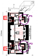
PCB layout
I'm astonished - like there isn't original F5 layout at all.
From picture I can see that input circuitry is kept away from high current pow supply-mosfets-output to loudspeaker loop.
Isn't it important ?
I'm astonished - like there isn't original F5 layout at all.
From picture I can see that input circuitry is kept away from high current pow supply-mosfets-output to loudspeaker loop.
Isn't it important ?
But Toshiba MOSFET's are not laterals...juma said:.............it's surely worth experimenting - especially if you have lateral MOSFETs at hand. ...........
They are very complementary verticals, with low Vgs threshold.
Tino
zinsula said:
But Toshiba MOSFET's are not laterals...
Tino
Yes, Hitachi make laterals. And Toshiba mosfets have high transconductance.
Sorry
Sorry for trying find out how to build one of these amps
Sorry for posting only three questions in this thread and only getting one answer(AndrewT).
Sorry for interupting all the anal geeks who don't wish to actually build anything. Just wish to discuss 'possibilities'
I'll just go elsewhere and buy a board off 'someone else' doesn't worry me in the slightest.
Maybe there should be a separate thread for people who just want to get this amp built. And are not interested in discussing how one particular part may sound .00001% better if it's replaced and facing 'north east' and the amp is switched on at 3mins past sunset on friday's at 25.575 deg above ambient room temp with a RH of 50% in December.😀
Re: Stupid Question
Hey Enzedone, lighten up, everybody seems to be in his own wave here, sometimes this happens.
Your tracks for the trimpots looks OK to me.
Cheers,
enzedone said:Is the track layout correct for P1 & P2?
Hey Enzedone, lighten up, everybody seems to be in his own wave here, sometimes this happens.
Your tracks for the trimpots looks OK to me.
Cheers,


zinsula said:
But Toshiba MOSFET's are not laterals...
They are very complementary verticals, with low Vgs threshold.
Tino
Hi Tino,
you are right - I stand corrected. Somehow, when I see 2SK or 2SJ mark i seem to automatically think of Hitachi's 2SK135 and 2SJ50 - the first power MOSFETs I used - decades ago.... 😀
Stupid Question - P1 & P2 Adjustment
Hi,
Before I switch it on.....
I am reading the F5 manual, under "Initial Adjustment".
"you will want to set the values of P1 and P2 to their minimum. Verify this with an ohmmeter"
Just to clarify, does this mean I want to initially set P1 & P2 to be 0 Ohms (or the lowest it will go)?
Thanks
Thermos
Re: Stupid Question - P1 & P2 Adjustment
Yup! zero ohms. Be sure to consider the output DC zero as the most relevant, and measure the volts across the resistors at output devices , the voltage at the input will not affect the final results. Not really important, it's important to get zero DC volts at the speaker output.
thermos said:Hi,
Just to clarify, does this mean I want to initially set P1 & P2 to be 0 Ohms (or the lowest it will go)?
Thanks
Thermos
Yup! zero ohms. Be sure to consider the output DC zero as the most relevant, and measure the volts across the resistors at output devices , the voltage at the input will not affect the final results. Not really important, it's important to get zero DC volts at the speaker output.
Re: Stupid Question - P1 & P2 Adjustment
According to my approximation, we will have final values of P1 and P2 at about 1K+something. So, I highly recommend you to start P1 and P2 values lower than 1K.
Be careful, if you have too high P1 and P2 values, the bias current easily goes up more than 10A . . . No good, even if the amp has the current limiter at 10A . . .
>> <<
<<
Good luck!
Cheers,
>>🙂<<
thermos said:
Just to clarify, does this mean I want to initially set P1 & P2 to be 0 Ohms (or the lowest it will go)?
According to my approximation, we will have final values of P1 and P2 at about 1K+something. So, I highly recommend you to start P1 and P2 values lower than 1K.
Be careful, if you have too high P1 and P2 values, the bias current easily goes up more than 10A . . . No good, even if the amp has the current limiter at 10A . . .
>>
<<Good luck!
Cheers,
>>🙂<<
- Home
- Amplifiers
- Pass Labs
- F5 power amplifier