h_a said:Choky's joking 😀
........
naahhhhhh

I learned one thing (besides few more ) observing Papa and his fun here - taking in account prescripted goals for each particular project , he really don't leave much space for any sort of (even just so-so) flaws.
that - taking in account even all obligatory and possible compromises he must make in commercial product , when commercial product is in case .
hehe
looking at various pics form his kitchen , he even use his own commercial products , not some special hotroded ones .......
so - that's not my intention to say that Papa's solutions are definitive in any way - I take them as bloody valuable lessons and spreadsheets (ya know that old story about fish and learning fishing) but more like as flawless starting points
dunno - I presume/resume that that exactly is his intention , besides few other
 ones ...........
naah .... I know that I didn't wrote all this in much understanding way , but I'm still under impressions of ystrdy's Laguna 😀
I think the most likely culprit is thermal drift. If you take the
thermistors out, the amp will drift more and the bias increases
with temperature.
Higher bias sounds better, but there are practical limits, otherwise
we would simply set it obscenely high and be done with it.
I suggest that you monitor the bias and the DC offset during your
listening sessions to see how constant they are.
😎
Choky, nice to see that we agree, even if your post starts with an disagreement 😀
Have fun, Hannes
Have fun, Hannes
woody said:Could it be that some brands of thermistors are noisier than
others ?
Could be different time constants.
I'll measure the noise with the Cantherm and EPCOs devices -- it's hot as hades here and a good excuse to come out of the garden...bunch of vandals tried to knock down our tomato garden last night...can't see as I blame them as the tomatoes are growing in the front lawn.
h_a said:Choky, nice to see that we agree, even if your post starts with an disagreement 😀
Have fun, Hannes
but you already knew that I'm never joking and I never agree .......
edit:
and I'm never Off Topic 😀
I will try to measure distortion with and without, but I remember THD is very close. The power resistors are Vishay dale 0,5Ω/5W and all the rest (except feedback) are vishay dale 1,4W metal film. Indeed the amplifier current drifts upwards after some time from 1,25A to 1,4A.
First of all... I would like to say good hollyday's to everyone inhere - I just returned from a nice holyday in the Netherlands with my family ...
It might be, that i wish to play with the F5! Perhaps there a BOM in here ??? ... And a nice pcb single sided ??? ... 😀 (I am to lazy to find it)
Best regards Jesper.
Kids finding way in Holland 😀
It might be, that i wish to play with the F5! Perhaps there a BOM in here ??? ... And a nice pcb single sided ??? ... 😀 (I am to lazy to find it)
Best regards Jesper.
Kids finding way in Holland 😀
Attachments

lykkedk said:First of all... I would like to say good hollyday's to everyone inhere - I just returned from a nice holyday in the Netherlands with my family ...
It might be, that i wish to play with the F5! Perhaps there a BOM in here ??? ... And a nice pcb single sided ??? ... 😀 (I am to lazy to find it)
Best regards Jesper.
Kids finding way in Holland 😀
Happy holiday Lykke.
But don't you have something else you ought to finish up? 🙄
Magura / Whom will have his Drek up and running by Sunday, worst case scenario!
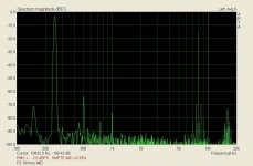
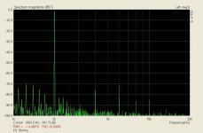
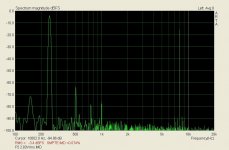
panos29 said:I found the distortion spectrum without the thermistor at 10V output 2KHz on 8© wirewound power resistor. I will try to put thermistors on during the coming days to do another spectrum analysis.
That's gonna be interesting.
Magura 🙂
Magura / Whom will have his Drek up and running by Sunday, worst case scenario!
first time you overrouled me
Jesper.
Panos -- your distortion spectra are an order of magnitude (actually more than) worse than that which I experience.
After delivering all the Fairchild FETs for the Group Buy, I finally got down to do some measurement of the FETs, and just finished measuring one amp tonight.
Apart from very different Vgs btw P and N devices, the transcoductances also differ by a factor of 1.7 at 2A bias. In comparison to the Toshibas, they are anything but complementary. See attached pdf.
But good. The bias was set at 1.5A per FET at the start, and went up to 2.3A in the end -- quite a bit worst than the Toshiba (1.75A -> 2A) on exactly the same heatsink, etc. Furthermore, the P and the N devices drifted differently with temperature, resulting in an DC offset in the end of something like 25mV. Not that it is an issue, as I am using the balanced version anyway, so they cancel out on both sides.
The frequency response is similar, with a very slight rise of 0.5dB at 600kHz. Probably still curable by fiddling with gate resistor values, etc.
More to follow. Bed time now. 😱
Patrick
Attachments
? for Nelson or anyone else...
What gauge (or thickness) metal is used for the top, bottom and rear plates on the F series amplifiers?
Thank you,
Chris
What gauge (or thickness) metal is used for the top, bottom and rear plates on the F series amplifiers?
Thank you,
Chris
What gauge metal is used for the top, bottom and rear plates on the F series amplifiers?
I'll be using 3/8" 1000 Alum. all around.
- Home
- Amplifiers
- Pass Labs
- F5 power amplifier