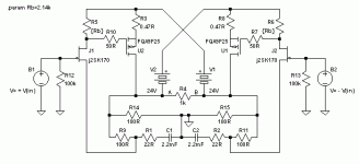
That amp already has DC feedback.juma said:
Yes, that looks nice on paper. Think of real world tubes and speaker protection.
... which was just what I did before I posted my findings initially. Without the 22R and caps (and without source-to-source gain resistor) it is a buffer with no voltage gain. With those 22R, the voltage gain is 1+100R/22R=5.5 (and in my variant it is 1+22R/3.75R=6.9)EUVL said:Had I not been still waiting for Fairchild MOSFETs, I would have built one without caps as per Circlomanen's circuit in post #1286. But maybe someone who spices regularly would care to do a quick sim, just to prove me wrong.
- Klaus
Now those R's are needed only when the inputs are left open or are cap-coupled. In terms of input impedance it would actually be better to go to GND, otherwise they get "reverse bootstrapped" as described in a previous post.juma said:Yes, ground seems a logical place for them, but I wanted to keep them referenced to JFETs' sources so they can swing together 😉
- Klaus
> With those 22R, the voltage gain is 1+100R/22R=5.5
Which is what I would expect. So you are saying that I can just take out those caps and the circuit works, probably with a much lower value of JFET drain resistor.
But I wonder what difference in bandwidth and distortion does the 2200uF caps make on their own ?
Patrick
Which is what I would expect. So you are saying that I can just take out those caps and the circuit works, probably with a much lower value of JFET drain resistor.
But I wonder what difference in bandwidth and distortion does the 2200uF caps make on their own ?
Patrick
Just Musing -- probing around with the scope -- a.c. coupled
P Channel MOSFET Gate Signal:
P Channel MOSFET Gate Signal:
An externally hosted image should be here but it was not working when we last tested it.
An externally hosted image should be here but it was not working when we last tested it.
Here's the N & P Channels together:
An externally hosted image should be here but it was not working when we last tested it.
Basically yes, with proper adjustment of values and ratios of all of the resistors.EUVL said:So you are saying that I can just take out those caps and the circuit works, probably with a much lower value of JFET drain resistor.
But, some new insights on the circlotron here (I had a gut feeling), there is a significant common mode problem at higher freqs (bias gets heavily modulated with higher odd order components), more or less regardless of topology details (that is, value of the GND load resistors and wether or not cap coupling or gain is used). This specific circlotron circuit is more tricky than it seems at first sight...
- Klaus
> there is a significant common mode problem at higher freqs (bias gets heavily modulated with higher odd order components), more or less regardless of topology details
I am afraid that I do not get what you are trying to say.
Could you elaborate a bit more?
Thanks,
Patrick
I am afraid that I do not get what you are trying to say.
Could you elaborate a bit more?
Thanks,
Patrick
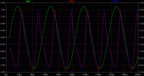
.... I get this response for the drain currents at 20kHz (and no speaker load, exept for those "bypasses" of (100R+100R)//(122R+122R). With 8R load it gets even nastier...
Distortion is accordingly high. BTW I tried cascoding the JFETs and buffering the MOSFET gate drive to lessen some capacitive effects, but to no avail. I'm quite puzzled about that behaviour.
- Klaus
Distortion is accordingly high. BTW I tried cascoding the JFETs and buffering the MOSFET gate drive to lessen some capacitive effects, but to no avail. I'm quite puzzled about that behaviour.
- Klaus
Attachments
I don't think we should jijack the F5 thread, so I propose to move the discussion back to Circlomanen's original thread.
🙂
Patrick
🙂
Patrick
I have built and tested such a circuit and I'm working on the article now. I will find an appropriate place to publish once finished.
hi,
i just saw F5 design. wow, very less parts and its easy for me to build.
i have few questions.
Q1 and Q2= can i use IRF9610?
Q3 and Q4 = can i use IRFP240?
is there at output have to place any resister like aleph-3?
how much heat dissipation will be on 50w output? let say i am using 8ohms speaker.
how about the cap for power supply?
thank you
michael
TH1 TH2
In regards to TH1 and TH2. I would like to use them. I got some wimpy little thermistors from Digikey.
http://parts.digikey.com/1/parts/indexd12209.html
Pretty concerned that these will melt from more than just temp. Do these thermistors see current? I thought I remembered seeing something about TH1 and TH2 needing to carry 10amps, but maybe this is from the power supply. Cant remember and have not seen that reference again. If someone could give me a bit of help I would appreciate it.
Had my FETs backwards. just found that mistake. Going through P2P again to recheck.
Thanks
Uriah
Nelson Pass said:And the value is not critical at that. I also use 3.3K, because I have
a bag of them.
In regards to TH1 and TH2. I would like to use them. I got some wimpy little thermistors from Digikey.
http://parts.digikey.com/1/parts/indexd12209.html
Pretty concerned that these will melt from more than just temp. Do these thermistors see current? I thought I remembered seeing something about TH1 and TH2 needing to carry 10amps, but maybe this is from the power supply. Cant remember and have not seen that reference again. If someone could give me a bit of help I would appreciate it.
Had my FETs backwards.
 just found that mistake. Going through P2P again to recheck.
Thanks
Uriah
space2000 said:hi,
i just saw F5 design. wow, very less parts and its easy for me to build.
i have few questions.
Q1 and Q2= can i use IRF9610?
Q3 and Q4 = can i use IRFP240?
is there at output have to place any resister like aleph-3?
how much heat dissipation will be on 50w output? let say i am using 8ohms speaker.
how about the cap for power supply?
thank you
michael
Michael, go to http://www.firstwatt.com/downloads/F5-om_sm-080527.pdf and you will have your answers. Last page is PS.
I used the 12,000uf caps from Steve at ApexJr and they are working great. Only $1.99 each. I used 12.
Uriah
Re: TH1 TH2

if these two little buggers ever see some substantial current , then something is definitely wrong ......
just use them and do not worry ; did ya see same critters in Papa's amp ? they are probably same looking .
😀
udailey said:
In regards to TH1 and TH2. I would like to use them. I got some wimpy little thermistors from Digikey.
http://parts.digikey.com/1/parts/indexd12209.html
Pretty concerned that these will melt from more than just temp. Do these thermistors see current? I thought I remembered seeing something about TH1 and TH2 needing to carry 10amps, but maybe this is from the power supply. Cant remember and have not seen that reference again. If someone could give me a bit of help I would appreciate it.
Had my FETs backwards.just found that mistake. Going through P2P again to recheck.
Thanks
Uriah

if these two little buggers ever see some substantial current , then something is definitely wrong ......
just use them and do not worry ; did ya see same critters in Papa's amp ? they are probably same looking .
😀
Couldn't think of a good place to post this.....
The mods can move it if they need to.
For the amplifier builders:
http://www.diycable.com/main/product_info.php?cPath=140_141&products_id=598
has a pretty good deal on transformers. This looks like it might work as an F series transformer if run at 240v. Just an idea,
Chris
The mods can move it if they need to.
For the amplifier builders:
http://www.diycable.com/main/product_info.php?cPath=140_141&products_id=598
has a pretty good deal on transformers. This looks like it might work as an F series transformer if run at 240v. Just an idea,
Chris
- Home
- Amplifiers
- Pass Labs
- F5 power amplifier

