I don't get it (as usual)
Why keep looking for J108/K370 if the higher power handling J74/K170 are way cheaper and easier to obtain ?
$75 for several pairs would already be insane.
Jack,
you're decadent enough to blend in perfectly at the E-side, us J's must have congenital savoir-vivre.
Why keep looking for J108/K370 if the higher power handling J74/K170 are way cheaper and easier to obtain ?
$75 for several pairs would already be insane.
Jack,
you're decadent enough to blend in perfectly at the E-side, us J's must have congenital savoir-vivre.
Re: I need parts !
Check out www.tech-diy.com.
That's were I get my matched parts. Has F5 kits ready to go, just add some signal resistors and PS.
Mike
dfagerstone said:Anybody find 2SJ108 or 2SK370? I found them for USD$ 75.00 each. thanks a bunch. Don
Check out www.tech-diy.com.
That's were I get my matched parts. Has F5 kits ready to go, just add some signal resistors and PS.
Mike
I don't see an advantage to 2SK370 over 170 and similarly
no advantage to 2SJ108 over 2SJ74. They are equivalent
parts except that the older parts have a higher dissipation
figure.
no advantage to 2SJ108 over 2SJ74. They are equivalent
parts except that the older parts have a higher dissipation
figure.
Although it was not discussed explicitly, it was hinted at multiple times that because of the assymetry between N & P devices for both JFETs and MOSFETs, the basic F5 circuit has to deviate from total symmetry (different MOSFET source resistors, different JFET drain resistors) between the upper and lower half, in order to get best distortion cancellation.
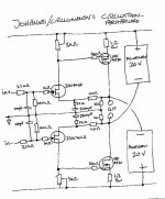
Then at the back of my mind, I thought I saw something at this forum before, with a similar topology, but only using only N JFETs and P MOSFETs. Of course that would be a circlotron, but like the F5 it also uses "current feedback", only that it is really perfectly symmetrical. Plus you get the balanced version using just 2 output devices :
http://www.diyaudio.com/forums/showthread.php?postid=489796#post489796
In my opinion, none of the caps are really necessarily. The actual resistor values, etc. might not be optimal, and you can probably also use P-JFETs and N-MOSFETs instead. But I do find the circuit very interesting, having built a variant of the balanced F5, and quite a number of circlotron type pre and power amps.
Patrick
Attachments
I moved one of the little buggers to a bigger heatsink which actually fits onto a nice black chassis -- it now oscillates at 197 kHz.
Hi Patrick,
as shown the circuit, without caps, would only have unity gain (buffer), according to a quick sim it performs quite well as such up to 16Vpp differential input (16 Wrms) into 8R (THD 1kHz 0.01%) and pretty low Zout, with F5-style operating conditions (24V supplies, 1.3A bias). The bottom resistors are parallel to the load and no bias current flows through them, only load current, thus their value is not important.
You need a source-to-source feedback resistor to get some gain when you want to go without caps, either directly or with two resistors going to the opposite load points. For the first variant see attachment, this gives 25Wrms into 8R with a 3Vpp differential drive (and 32V Vds at the 170's). The nice thing is that it self-balances perfectly, you can ground on input and double up the drive condition at the other and get 100% identical circuit conditions. 1kHz distortion is not as good though (but I haven't try to tweak much), 0.12% at these conditions, Zout at about 200mR.
The second variant is slightly worse 0.17% and even more sensitive to slight source resistor mismatches (1% mismatch is enough to greatly disturb leg current balance). Note that the input resistors get "reverse bootstrapped" by the circuit gain, so 100k will give only resulting 19k Zin, per side. This can be fixed by proper bootstrapping (divider taps accros the load at the gain ratio).
Also note that this circuit (less the supply) is practically the top half of the circuit TimS posted here as his balanced F5 approach. Last not least the circuit is basically identical to the original from Circlomanen, since "GND" is nothing else than the load center point and placing DC-blocked resistors to that point is equivalent to coupling from source to source, preferably also with a blocking cap to get DC unity gain. His one sims, slightly better than my proposal, at 0.07%, because the I/V-resistor is three times bigger (and JFET Id three times lower, only 3mA). It doesn't have the self-balancing action, though (which needs the "floating" gate resistors to work).
- Klaus (lover of circlotrons)
Attachments
I'll have to look closer at this and report back with my findings. And I'm pretty sure that it's just like you say.... because who am I to tell the Inventor what's X and what's not... 😀Nelson Pass said:What is the phase of the spike at the various points? in the X
case, we are looking for the spike to have the same absolute
phase on both halves. In the non-X case where the amps
share a feedback shunt resistor, it would have the spike out of
phase on both halves.

- Klaus
Ah, sorry, forget about that. It will only work in the ideal world, or perhaps when battery powered and truly floating. Otherwise the smallest noise current mismatch in the 100k's will disturb everything...KSTR said:The nice thing is that it self-balances perfectly, you can ground on input and double up the drive condition at the other and get 100% identical circuit conditions.
- Klaus
Ed LaFontaine said:
Mongo is a scientist
A sad week in that Harvey "Hedley" Korman passed away.
"Work, work, work..."
or, from the History of The World Part I "Hump or Death"
my new motto "It's good to be the King".
If you blow out the ZTX450/550's it will oscillate (at least mine did)-- I replaced them and rebiased the amplifier and everything is OK.
And George Carlin.
Interestingly, I get a little lower distortion with the bipolars sitting
in there as limiters. The very slight non-linearity they offer is in
opposition to the natural distortion of the circuit, giving a little 3rd
harmonic cancellation.
😎
And here's what the sun looks like through all the smoke from the
surrounding forest fires:
Attachments

PassDiy .....sweet facelift!!
Hey, if there's any danger to your property, I know of a great safe place you can send everything
And here's what the sun looks like through all the smoke from the surrounding forest fires:
Hey, if there's any danger to your property, I know of a great safe place you can send everything
> For the first variant see attachment,
I could not see any attachment for 1st & 2nd variant ....
😕
Patrick
I could not see any attachment for 1st & 2nd variant ....
😕
Patrick
Power supply for F5
Almost done with my power supply. I put together a little Picasa Album of the build and if you are a super noob, like me, this might be helpful. If I goofed anything please let me know guys.
Uriah
http://picasaweb.google.com/udailey/F5PowerSupplyBuild
Almost done with my power supply. I put together a little Picasa Album of the build and if you are a super noob, like me, this might be helpful. If I goofed anything please let me know guys.
Uriah
http://picasaweb.google.com/udailey/F5PowerSupplyBuild
Nelson Pass said:
Interestingly, I get a little lower distortion with the bipolars sitting
in there as limiters. The very slight non-linearity they offer is in
opposition to the natural distortion of the circuit, giving a little 3rd
harmonic cancellation.
Well that is facinating information (well, at least to a newbe like
me)! In my spice simulations, the current limiting section of the
circuit _adds_ in the ballpark of an order of magnitude of THD
(even when the output is no where close to where the transistors
start conduction).
If one could generalize, how much do the simulations vary from
the real thing?
thanks,
Robert
i bought some toshiba 2sk170bl and 2sj74bl from ampslab-do i have to match the ones i put in a F5? and could someone steer me to an article on how to do it ? thanks bubba
audiorob said:
Well that is facinating information (well, at least to a newbe like
me)! In my spice simulations, the current limiting section of the
circuit _adds_ in the ballpark of an order of magnitude of THD
(even when the output is no where close to where the transistors
start conduction).
If one could generalize, how much do the simulations vary from
the real thing?
thanks,
Robert
With the thermal comp in my F5 I get THD+N% a little over 0.003% @1W. No trimming of the JFET source resistors either.
audiorob said:If one could generalize, how much do the simulations vary from
the real thing?
A lot depends on the quality of models. The Mosfet models are
understood to be the least accurate. I have seen up to 10 to 1
variations in distortion depending on the real Mosfet and the
model.
I have seen simulations from over in the Solid State forum where
a constant Vds JFET yielded pure 2nd harmonic, but on my bench
I have not been able to duplicate that - there is always some 3rd.
I personally do not depend on simulations to predict distortion
in circuits. I prefer to build them and see, although it is also
interesting to compare the results to sims.
BTW, I got about .003% on my first channel, and having built a
few now, it appears that the simple majority of them hit this
without tweaking.
- Home
- Amplifiers
- Pass Labs
- F5 power amplifier