Looping in and out through the same soundcard will cause the 50Hz+ to be visible on ARTA. You can use a recorded impulse if you want to avoid this, RMAA does allow. Never tried with ARTA, have two soundcards for this purpose.
50 Hz and its multiples are not the problem. They aren't appearing in the soundcard loopback test.
They are really present in the F5 output signal. You can even hear them in loudspeaker with no input signal.
My question was: why do H2 and H3 look different on the oscilloscope and ARTA?
They are really present in the F5 output signal. You can even hear them in loudspeaker with no input signal.
My question was: why do H2 and H3 look different on the oscilloscope and ARTA?
Hook the scope onto the ARTA test so your performing a simultaneous test with the scope and ARTA. Do results still vary?
I'd also do the above again with the amp removed from the test setup and see how the scope and ARTA compare.
What resistor(s) are you using for the dummy load?
I'd also do the above again with the amp removed from the test setup and see how the scope and ARTA compare.
What resistor(s) are you using for the dummy load?
Last edited:
Dummy load is a wirewound resistor 50 W with inductance 1.6 uH (microH, I measured it myself🙂), which is negligible.
Simultaneous testing doesn't help, you could try it, but it will give the same results.
Resolution of a scope. That could be the real reason. Vertical there is max 80 dB in 10 dB steps on the scope.
According to ARTA H2 and H3 are below -80 dB, but the scope says -53.5 dB.
It is similar in your measurement (at #16532) - REW shows H2 > H3 both below -80 dB, but the scope says H2 < H3, level vertical?
How do you interpret this?🤔
yes resolution can at times be a problem on older gear. Have you tried X1 prong, also if possible raise the test power.
Last edited:
I put that down to my laptop's sound card and the voltage divider I used.. its probably a combination of them and the settings I used in REWIt is similar in your measurement (at #16532) - REW shows H2 > H3 both below -80 dB, but the scope says H2 < H3, level vertical?
How do you interpret this?🤔
I bought a new scope and it's results mirrored my old scope nicely, so I'm taking my scope results as being correct, besides I've more experience with scopes than REW. One thing I have done.. but not with REW and I should, is I've a little tank circuit I built and tuned using a VNA that I know is bang on the money. To be sure I'm setup correctly I use this to pilot test my scopes before testing gets underway.
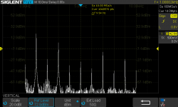
Here's an example of a scope not quite setup correctly. This is on my new scope, note its showing ~25dB H3>2, I need to revisit it. I'm guessing my scope impedance setting was not correct.. that can make a difference in dB levels. Regardless though if you look at the results from a relative ratio perspective as apposed to actual dB levels, its bang on with my old scope. So personally I dont take much away from dB levels indicated, instead so long as H2->3 ratio's correlate I'm happy
Attachments
Last edited:
I cannot see any valid sine. It looks more like heavy clipping or square wave, or so.
If test sine 1 kHz is at level about 30 dBm = 1000 mW = 1 W and H3 at about 0 dBm = 1 mW,
then it is definitely too much. I don't even want to think about THD value, regardless all other harmonics.
There is a worm in your test setup😉. Make a double check and try again.
If test sine 1 kHz is at level about 30 dBm = 1000 mW = 1 W and H3 at about 0 dBm = 1 mW,
then it is definitely too much. I don't even want to think about THD value, regardless all other harmonics.
There is a worm in your test setup😉. Make a double check and try again.
I have a question relating to P3 adjustment and the measurement of this with a digital oscilloscope, do I need a differential scope probe to isolate the output terminals from earth? I tried this measurement a year or so ago and blew one of the power resistors and assume it was because I shorted one terminal to earth through the oscilloscope? I want to try this measurement again, but this time without damage.

The purpose of the gain trimmer (so called P3) is to allow you to adjust the relative closed loop gain of the top and the bottom halves of the F5 circuit.
In doing so, it allows you, with your particular combination of JFETs and MOSFETs, to balance the gain such as to maximise even harmonic distortion cancellation.
In particular, if you do not have matched devices between the two (stereo) channels, it allows you to compensate the difference to an extent.
A digital oscilloscope is primarily an equipment to allow visualisation of a signal in the time domain.
Very few of them have resolution much higher than 8 bit, not to speak of 16 bit or 24 bit.
They also do not have the required linearity to allow distortion measurements to much better than 0.1% (-60dB).
To be able to make proper use of P3, you need to be able to measure distortion to much better than -100dB.
And that means a low-distortion oscillator AND a distortion analyser (or sound card) to at least -110dB or better.
My 2 cents,
Patrick
^Patrick’s explanation is the simplest and clearest I've seen it said. 
Finding a scope with better than 8-bit vertical resolution is very rare and expensive, the easiest solution is something like REW software and a USB microphone interface like a Focusrite or Tascam.
XRK971 started a very good thread here - https://www.diyaudio.com/community/threads/howto-distortion-measurements-with-rew.338511/
Patrick, I totally agree, oscilloscope is not suitable here. Nevertheless, Allan managed to create an exemplary spectrum for F5 (#16532) using oscilloscope and everyone cheered, me too . How is it possible?🤔
. How is it possible?🤔Is it a spectrum of the F5, or spectrum of the scope ADC ?
Or a combination of both ?
All is fine if you believe what you see.
Just ignore my posts.
🙂
Cheers,
Patrick
Or a combination of both ?
All is fine if you believe what you see.
Just ignore my posts.
🙂
Cheers,
Patrick
Hello out there,
in Germany we have a saying:
'Wer misst, misst Mist.'
Would have a meaning like:
Who measures, measures damn...
Only a little joke. 🤔
Cheers
Dirk
in Germany we have a saying:
'Wer misst, misst Mist.'
Would have a meaning like:
Who measures, measures damn...
Only a little joke. 🤔
Cheers
Dirk
So don't measure, not even with a DMM.
I am sure you can feel the bias with your fingers, and listen to DC offset with your ears.
And just listen for distortion.
If you cannot hear, then it does not matter.
Right ?
😉
Patrick
I am sure you can feel the bias with your fingers, and listen to DC offset with your ears.
And just listen for distortion.
If you cannot hear, then it does not matter.
Right ?
😉
Patrick
I think it was Jim Williams who said: "A digital scope doesn't lie, but it doesn't always tell the truth"
One of the ways to circumvent the issue of low dynamic range is to use a notch filter to null the fundamental coming into the FFT apparatus.
One of the ways to circumvent the issue of low dynamic range is to use a notch filter to null the fundamental coming into the FFT apparatus.
You have to choose the right tool for the job ... and for measuring distortion, a digital scope isn't it.
I was surprised how good and inexpensive a serious distortion measurement rig is - just a Focusrite 2i2 or Solo, an attenuator, and REW on a laptop is perfectly fine in the audio range for all but the most distortion-free devices ... 🙂
"Wer misst, misst Mist" - as a former experimental physicist, I learned that it is important to know the limitations of all your devices in the chain to know where and how much "Mist" (literally dung ... meaning unknown uncertainties) occurs ... I fell for an easy assumption myself, ignoring that, using my Rigol DSO's FFT function to measure the distortion spectrum of my 2A3 SE tube amp. It came out to about 1% 2nd order distortion (-40 dB) at 1 W output, which sounded plausible at the time, because, you know, it is an 2A3 SE ... and I didn't inquire further.
Later, when I also had a Focusrite 2i2 to compare, I actually found out that my DSO was good to -60 dB (0.1%), and it wasn't the 2A3 SE either that was 1% ... it actually is my function generator, a nice little old Tektronix CFG250 that has 1% distortion - and it even says so in the specs in its manual, if one would have looked !
Regards, Claas 😉
how about
forget about using a scope to set P3. Instead using a DMM measure and match the resistance over R3 and R4 with amplifier off. This will centre P3.
If you want to scope the output for FFT ect then be absolutely sure your amp is ground referenced (F5 are), then make sure the probe earth only goes to output negative (-)..
I have a question relating to P3 adjustment and the measurement of this with a digital oscilloscope, do I need a differential scope probe to isolate the output terminals from earth? I tried this measurement a year or so ago and blew one of the power resistors and assume it was because I shorted one terminal to earth through the oscilloscope? I want to try this measurement again, but this time without damage.
forget about using a scope to set P3. Instead using a DMM measure and match the resistance over R3 and R4 with amplifier off. This will centre P3.
If you want to scope the output for FFT ect then be absolutely sure your amp is ground referenced (F5 are), then make sure the probe earth only goes to output negative (-)..
Last edited:
- Home
- Amplifiers
- Pass Labs
- F5 power amplifier