Thank you for the answer and measurments. I didn't think anyone would answer anymore.
P3 in my F5 is exactly centered by resistance so the harmonics in both channels look almost equal.
The difference between H2 and H3 is equal 20 dB (-74 dB for H2 and -94 dB for H3).
Yesterday I rechecked the bias and offset after two months from the 1st take off and
there weren't any deviations (0.6 V bias and offset < 1 mV in both channels). Wow!
So I made up my mind not to touch any pot. I want to give it a few more weeks to convince myself
that the sound is the way I like it. I know that cancelling of H2 and the other even harmonics
could make the sound very different😉.
My prefered sound is a warm one with analytic touch, so that every instrument can be identified at its right place
as my old tube amp in ultralinear design does. Its frequency spectrum looks like this of F5.
I was wondering about the higher noise in the left channel as you mentioned. An explanation could be 50 Hz from my
LCD display, keyboard and mice that were directly placed in front of the left side of F5.
I'm curious what the harmonics look like when you will exactly center P3 by resistance.
Attachments

If you want -74dB H2, why choose a push-pull amp ?
Why not just build something single ended, like a J2 or a F8 ?
Patrick
Why not just build something single ended, like a J2 or a F8 ?
Patrick
Yes, I have used snubbers recommended by danny_66 for Toroidy TS400VA (#108 at Quasimodo results thread):Do You have snubbers for the transformer?
Rs = 13R
Cs = 150 nF
Cx = 10 nF
I don't say I want -74 dB H2. I have built my F5 and measured H2 at this level with P3 centered exactly by resistance.If you want -74dB H2, why choose a push-pull amp ?
Why not just build something single ended, like a J2 or a F8 ?
Patrick
Now I am evaluating the sound looking for what I like and appreciate any experience builders made tweaking P3.
Why not single ended? A good question.
The main reason is the electrolytic output condenser. I remember my first amp from the seventies with a large elco at output
and was wondering if it is really transparent for the whole audible spectrum. Then came DC-coupled amps which I found better.
This is my own opinion only and I don't want to start any discussion about pros and cons of output elcos.
BTW F8 is not published yet.
The J2 is single ended (i.e. not complimentary push-pull) and DC coupled.
The original F8 has a coupling cap, but there is a working version which is DC coupled.
https://www.diyaudio.com/community/threads/first-watt-f8.358672/post-6654823
They both have high H2's.
Patrick
The original F8 has a coupling cap, but there is a working version which is DC coupled.
https://www.diyaudio.com/community/threads/first-watt-f8.358672/post-6654823
They both have high H2's.
Patrick
Dennis,mamsterla,
The store has the 6mA to 8mA Idss jfets available: https://diyaudiostore.com/collections/frontpage/products/matched-jfets?variant=39335247020105
Those will be fine for an F5.
Edit: Also, may I suggest you use a higher power resistor (say 2W) for the 10 ohm source resistors for the jfets (R3 and R4) in the schematics on page 2 here: https://firstwatt.com/pdf/art_f5_turbo.pdf . The reason is that as the voltage level approaches clipping (near +/-20-ish volts), the peak dissipations at R3 and R4 are over one watt.
Thanks for the construction hint. I will make sure to put in some higher wattage resistors in R3/R4. I already ordered the punkydawgs items since I moved quickly on it. I am going to be receiving all the elements in the next couple of weeks and organize my thoughts.
I am looking for suggestions on hookup wire and whether to use a copper bus bar for a star ground in the PS construction.
shall doMy two cents: let it run for >1h before doing any measurements!
@ACnotDC
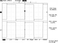
I was pressed for time, so with P3 now centred by resistance ran my F5 distortion check using an oscilloscope instead of REW.. bias 0.61V, sink temps ~48 degC, 8 ohm load. Have also attached the First Watt F5 distortion which my amp compares against nicely. Will retest using REW when I've the chance so we've continuity in test acquisition to compare against my earlier REW measurement when P3 was centred by turns.
Note: I had to increase the test wattage to ~2 watts before the scope would plot the harmonics. Not sure if it was a scope setting or the noise hid the harmonics at 1 watt. I've a new scope with coffee & waffle abilities plus bode & better probes coming so will put it through its paces once in hand & post its results
Comments welcomed
edit: just realised I should've also checked using square wave.. will include in the next round of tests & post up
Attachments
Last edited:
for those wondering..
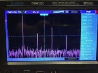
I had a good 3hr listening session last night with P3 centred by resistance, plot attached (using scope).
Compared to earlier when I had P3 centred by turns (REW plot attached) the bass is now a little leaner, instrument separation is better defined, brass instruments seem crisper and have more body / more complete plus the stage has better depth. It sounds very very nice but I think I'd prefer it more if I can land the distortion in the middle of where it was, and where it sits now. I finished off the session with some Lynyrd Skynyrd country rock, they haven't sounded this good in a long time.
So I think my target is H3 ~6dB > H2. I'm using ProAc Studio 125's which are a typical Xmas cherry sweat ProAc sound. Oh how I wished I still owned those ProAc Response 3.8's!
Attachments

Last edited:

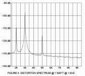
yes I was mighty happy to see that, it reassures you thats for sureCompared with the original (from the F5 manual).
Patrick
.
.. think Nelson maybe ahead in the dressage though, for now 😎
Attachments

Last edited:
and please nobody comment on the PSU layout, I know I know!
Its going to be interesting what comes to the table once its cased and arranged correctly 😉
Its going to be interesting what comes to the table once its cased and arranged correctly 😉
Last edited:
@Allan
Many thanks for the measurments and congratulations. They are like out of a picture book of F5.
This is what I was expecting when doing my measurments. But I can't explain today why they are so much different.
On the other side it is very strange because the spectrum is the same in both channels of my F5.
The power MOSFETs sind standard IRFP240 and IRFP9240 from F-5 TRANSISTOR KIT of diyStore.
Next time I have to check if P3 is really center by resistance. I know I did it with ohm-meter before I mounted it in.
It is very interessting what is the whole THD + N in percent in your F5. Could you post it?
My old scope TDS360 has a rudimentary FFT function too. Next time I have to test it. Maybe it is even usable.
The description isn't very promising. Has anyone try it yet?
Greetings from Germany
Adam
Adam,@Allan
Next time I have to check if P3 is really center by resistance. I know I did it with ohm-meter before I mounted it in.
It is very interessting what is the whole THD + N in percent in your F5. Could you post it?
My old scope TDS360 has a rudimentary FFT function too. Next time I have to test it. Maybe it is even usable.
The description isn't very promising. Has anyone try it yet?
Greetings from Germany
Adam
passive re-centre P3 with equal resistance across R3 & 4... then watch your bias next time you power up, you may have to adjust it
So far I haven't played much with THD so still some learning but will look into that for sure
Sorry I'm not familiar with your scope. Try searching for scope FFT demo and include your scope model and if not try scope brand !?!
Salut from Oz

Last edited:
Adam,
as an exercise, I turned P3 all the way to its stop then wound it back to centre by count. I then measured the resistance across R3 & 4.. it was out.
I then did the same again in opposite directions, I got the same resistance error however it flipped 180deg., as you'd expect.
So it seems when your on a stop then wind the pot in the opposite direction, the pots slider doesn't immediately take up on its thread so you loose accuracy in your count back to centre.
I then measured the difference between H2 & 3 when centring P3 "by count" from opposite directions, I got ~18dB difference. So its fare to say if I've centred P3 by count from the opposite direction you did, our results could differ by ~18dB and dont forget we haven't factored your P3 error value either, so the difference between our amps could even be higher! These numbers are rough because as expected the bias changes with any change in P3, to speed this test up I deliberately didnt re-bias properly after each centring
Last edited:
Allan,
because I felt so motivated by you, my F5 come on the workshop table.
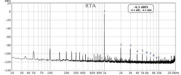
I tuned P3 to get minimum of H2. So H2 was decreasing from -74 dB to -87 dB.
H3 is still about -96 dB. THD + N is now 0.0085%, compared to 0.029% before.
This is the lowest distortion + noise that could be achieved, besides my sound card
itself shows 0.0011% THD + N.
P3 is a 12 turn trimpot and I needed to do one half turn only, convinced me that
it was nearly perfectly centered. The change is about 8R and is not big deal
having the parallel connection to 10R resistors.
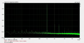
Then I checked the spectrum once again with my old Tek TDS360.
The FFT output on this oscilloscope is pretty noisy and the frequency components
look a little bit different comparing with ARTA.
Why is this the case?
I leave this as an exercise for all reader of this thread. 😉
because I felt so motivated by you, my F5 come on the workshop table.
I tuned P3 to get minimum of H2. So H2 was decreasing from -74 dB to -87 dB.
H3 is still about -96 dB. THD + N is now 0.0085%, compared to 0.029% before.
This is the lowest distortion + noise that could be achieved, besides my sound card
itself shows 0.0011% THD + N.
P3 is a 12 turn trimpot and I needed to do one half turn only, convinced me that
it was nearly perfectly centered. The change is about 8R and is not big deal
having the parallel connection to 10R resistors.
Then I checked the spectrum once again with my old Tek TDS360.
The FFT output on this oscilloscope is pretty noisy and the frequency components
look a little bit different comparing with ARTA.
Why is this the case?
I leave this as an exercise for all reader of this thread. 😉
Attachments

- Home
- Amplifiers
- Pass Labs
- F5 power amplifier