I ordered some 2SJ618/2SK3497 from digikey, but I'll have to wait a while before I get them. I'm looking forward to play around with them - they are relatively new, so there is not much info on them on the forum.
Looks interesting -- forward conductance is nearly twice the IRF parts -- but input cap is a lot higher as well.
Post 6883 A Wayne... he shows heatsinks intended for LED lighting products... I'd not run fans myself, since they add noise to the room. One might get away with a squirrel cage blower running off a much much much slower (&quieter) motor, and ducted to run air up and along the fins. It doesn't take that much air to greatly improve the effective heat transfer... one could turn the thing on with a thermal switch too...
One could approximate their size by "unwrapping them" and figuring the thermals for a 3" high and X" wide heatsink of similar fin construction... probably still not enough heatsink.
_-_-bear
One could approximate their size by "unwrapping them" and figuring the thermals for a 3" high and X" wide heatsink of similar fin construction... probably still not enough heatsink.
_-_-bear
One could approximate their size by "unwrapping them" and figuring the thermals for a 3" high and X" wide heatsink of similar fin construction... probably still not enough heatsink.
_-_-bear[/QUOTE]
I'm trying to find out what the power dissipation is on those heat sinks... I know the highest output for one of the arrays that can go on that heat sink is 56 watts. So, if I can get some dissipation numbers on those arrays, then maybe some assumptions can be formulated. Does anyone have any figures on what the max dissipation is on the output devices in the F5 at around 25C?
it's all in the pdf.Does anyone have any figures on what the max dissipation is on the output devices in the F5 at around 25C?
dissipated power = bias current times voltage across the FET.
HI Andrew!
Okay... I'll bite.
"the F5 is a push-pull ClassA amplifier that when biased to 1.3A can deliver ~2,6Apk of ClassA current to the load.
If the load is 8r0 then the maximum ClassA power is 27W ([2 * 1.3]^2 * 8 / 2)"
Andrew T.
"BTW,
27W is equivalent to 54Wpk. i.e. both are 20.8Vpk and 2.6Apk into 8r0."
Andrew T.
Does this mean both devices +/- are at 54Wpk? For a total of 108W per channel? Does that mean both channels would dissipate 108Wpk?
Mr Pass says that the F5 power consumption is 180W 8ohm @ 25W
How do these numbers relate?
do you want output power to the load?
or
do you want dissipated power to the heatsink?
Don't confuse the two.
or
do you want dissipated power to the heatsink?
Don't confuse the two.
do you want output power to the load?
or
do you want dissipated power to the heatsink?
Don't confuse the two.
It would be the dissipated power to the heat sink... I'm trying to relate it to other heat sinks... If I can find out their dissipation as well.
Choke Loading an F5
What happens when the output of an F5 is choke loaded (with a big @ss choke)?
I know the output impedance changes to whatever the parallel inductor is...but is a coupling cap (always) required as well?
Thanks in advance,
Chris
p.s. threads of interest that deal with similar questions:
http://www.diyaudio.com/forums/pass-labs/24737-choke-loads-zen-aleph-amps.html
http://www.diyaudio.com/forums/pass-labs/30717-choke-loaded-zen.html
Last edited:
The F5 is a symmetrical push pull, not a single ended amplifier.
What do you mean?
A transformer as output load?
What do you mean?
A transformer as output load?
I am OBVIOUSLY sleepy.
In that case I guess I am talking about making it transformer coupled. Anyone tried it besides Tim Paravacini and Mac?
In that case I guess I am talking about making it transformer coupled. Anyone tried it besides Tim Paravacini and Mac?
Last edited:
even if I am always and obviously biased regarding iron - that's pretty bad idea in this case .
to explore virtues of OPT , one must deliberately construct amplifier intended for that concept .
to explore virtues of OPT , one must deliberately construct amplifier intended for that concept .
yup ;
perfect example ;
one of recent is also Magura's Donut amp
I've been looking at heatsinks and I was wondering about using this one... well two of them in each monoblock. Can anyone tell me based on the information provided if these look plausible to use? I don't know anything about thermal dynamics... but many here seem to. They are used for high output led lighting, which I know gets very hot too. They are almost 3 inches thick and about 6 inches around.
eddie
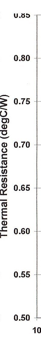
The last graph already shows the thermal resistance of the heatsink.
(thermal dynamics 101 : the thermal resistance number depends on the temperature difference between heatsink and ambient. The higher the temp difference, the higher the efficiency of the sink)
Theoretically they look very plausible.
The outer ring consists of 36 ribs of 30mm length, 36 times 30mm times 75mm heatsink height makes 810 sq cm.
Times two sides makes 1620 sq cm cooling area, or ~250 sq-inch.
Comparative example : an SK53 heatsink of 100mm height roughly has a total air exposed surface of 1150 sq cm, aka ~180 sq-inch.
An SK53 of 100mm height does a thermal resistance factor of ~0.70 C/W.
Practical problem for the power-LED heatsink is how to attach the power device to the inner ring, preferably in a thermal efficient way.
My first random cranial hickup would be to ram a round solid aluminum bar through the peep hole, and screw the power transistor on the solid core.
Attachments
Last edited:
My first random cranial hickup would be to ram a round solid aluminum bar through the peep hole, and screw the power transistor on the solid core.
I was wondering how would be best to mount to this sink. Nice idea! Now he has to get the right size round bar but thats nice solution.
right size round bar
2.25" diameter by the looks of the drawing, standard size.
Throw the heatsink in the kitchen oven at a few hundred C and the bar in the fridge for an hour.
Then slide the bar in the heatsink and Dick's your uncle.

2.25" diameter by the looks of the drawing, standard size.
Throw the heatsink in the kitchen oven at a few hundred C and the bar in the fridge for an hour.
Then slide the bar in the heatsink and Dick's your uncle.
That's a warm mama and your cold uncle Dick, Jacco!😀
The last graph already shows the thermal resistance of the heatsink.
(thermal dynamics 101 : the thermal resistance number depends on the temperature difference between heatsink and ambient. The higher the temp difference, the higher the efficiency of the sink)
Theoretically they look very plausible.
The outer ring consists of 36 ribs of 30mm length, 36 times 30mm times 75mm heatsink height makes 810 sq cm.
Times two sides makes 1620 sq cm cooling area, or ~250 sq-inch.
Comparative example : an SK53 heatsink of 100mm height roughly has a total air exposed surface of 1150 sq cm, aka ~180 sq-inch.
An SK53 of 100mm height does a thermal resistance factor of ~0.70 C/W.
Practical problem for the power-LED heatsink is how to attach the power device to the inner ring, preferably in a thermal efficient way.
My first random cranial hickup would be to ram a round solid aluminum bar through the peep hole, and screw the power transistor on the solid core.
The center section is solid... there is no hole in the heat sink... how does this affect the exposure calc?
Here's the item at Digi-key http://search.digikey.com/scripts/DkSearch/dksus.dll?Detail&name=521-1076-ND
Last edited:
- Home
- Amplifiers
- Pass Labs
- F5 power amplifier