Yes, exactly. Although I'd rather do it in a bottom layer with a straight wire. Once soldered, it will not move so those loops you have are not really necessary.
Repair pic
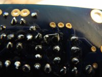
Okay Peter, I have repaired from the bottom as you suggested. The original "loops" were just so the wire wouldnt move when then tip touched it. I put it on so well I'm having difficulty removing it!
Just in case, is it possible to buy just one board? Really no big deal if I need to purchase 2 at the time, very reasonable and who knows? Maybe I'll screw something else up by then.
Thanks again,
russellc
Attachments
Never mind about the one board question, reading page 1 has all the info. If you will sell one, inform me and I'll pick it up to go with the spare I'll have. I have pay pal'd you for another pair of boards, I also ordered another channel of parts from Tech-DIY. Now I will have plenty of spares for future errors/explosions. If I dont need them, I'm sure another member out there may have similar difficulties. Plus, I have a feeling this wont be the last one of these I'll buy. Tech-DIY is an awfully friendly place, bundling all this up for a single purchase point. They have already sent out the only two tiny pieces that were missing. It must be a nightmare to bag up all this tiny stuff.
Russellc
Russellc
Last edited:
No problem, I will include one spare board with your order.
Let me know additional cost. You should have received a pay pal for the stereo pair, I will pay pal any difference.....assuming you got it of course,
let me know.
russellc
No problem, I will include one spare board with your order.
Does the repair look acceptable? or should it be reworked?
Thanks...
Russellc
Peter,
Do you have any stock left on the F5 boards? To cute not to have a couple tucked away just in case.
Thanks
Bill
Do you have any stock left on the F5 boards? To cute not to have a couple tucked away just in case.
Thanks
Bill
He keeps them in his wallet and passes them out as business cards.
They are actually slightly smaller than a business card! Amazing little package to be sure.
Russellc
Peter, I am very sorry but I have another beginners question. There is a lot of confusion, ( actually everyone is very sure of their way, just none of them agree with each other, making the thread useless for my purposes on THIS issue) over on the F-5 thread. My question concerns how the pot should be set on YOUR boards for startup: Full clockwise, or full counterclockwise? ( I thought I wasnt confused until I read everything, many opinions only one right way.
Thank you for answering what shouldnt be a question!😀
Russellc
Thank you for answering what shouldnt be a question!😀
Russellc
Peter, I am very sorry but I have another beginners question. There is a lot of confusion, ( actually everyone is very sure of their way, just none of them agree with each other, making the thread useless for my purposes on THIS issue) over on the F-5 thread. My question concerns how the pot should be set on YOUR boards for startup: Full clockwise, or full counterclockwise? ( I thought I wasnt confused until I read everything, many opinions only one right way.
Thank you for answering what shouldnt be a question!😀
Set them half way and you'll be fine either way, that's what I did and it worked fine for me 😉
IIRC, when mounting trimpots on my boards according to screw position on a footprint, you will be reducing bias by turning them clockwise (analogy to shutting the water).
Last edited:
Hi Peter.
I received my boards today. They are beautiful! Great job!
Thank You very match.
Cheers.
I received my boards today. They are beautiful! Great job!
Thank You very match.
Cheers.
Hello All,
I'm using Peter's PS boards- Pos and Neg for each channel. Also using small rectifier boards that accompany the PS boards and using one 18+18v transfo. I would like to know what is the best way to power the PS filter sections. Do I tap off the two rectifier boards and feed DC to both filter sections or take the AC from the transformer and feed 4 rectifiers? I'm guessing that taking the AC from the transformer and feeding 4 bridges would provide most seperation. What do you think?
Thanks,
Vince
Last edited:
Whenever using single transformer I use a single set of rectifier diodes, the filter banks can be separate for each channel.
Thanks!
I'll try it your way, Peter. Less drilling, less parts and more space in the box this way. Now I have to decide what to do with the other 8 soft recovery diodes! How's that AX-J PCB coming along! 😀
I'll try it your way, Peter. Less drilling, less parts and more space in the box this way. Now I have to decide what to do with the other 8 soft recovery diodes! How's that AX-J PCB coming along! 😀
- Status
- Not open for further replies.
- Home
- Group Buys
- F5 pcb group buy...