Those are Caddock MK132 (grey) and Vishay S102 (black). Both available from Percyaudio.com, although a bit pricey.
Thankyou Peter, fortunately there are very few of them.😀
Russellc
F5 boards and PS boards
I would like to order F5 and PSU boards for one amp.
Would you send me an info how much and were to pay?
I would like to order F5 and PSU boards for one amp.
Would you send me an info how much and were to pay?
Yes, I have plenty of boards in stock, also PS boards.
Those are Caddock MK132 (grey) and Vishay S102 (black). Both available from Percyaudio.com, although a bit pricey.
Hello Peter ,
Price and info on where and how to purchase ...
Regards,
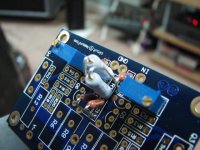
R1 and R2 resistors in Tech-DIY F-5 kit. Is this OK?
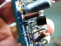
For R1 and R2 in my Tech-DIY F-5 kit I received the pictured resistors, 10 ohm 2 watt. The Daniels board has very small resistor locations, and has been discussed before, sometimes the resistors have to stand up. When it came to R1 and R2, there diameter would not allow them to stand side by side, so by offset mounting them, I can get them to fit. Question: I keep wondering if maybe
The caps were spec'd or selected wrong? I will also email Tech-DIY, but I figured this had come up before and is no biggie. I just didnt see the need for a 2 watt resistor in this location?
These arent soldered in place yet, so no big deal if anyone sees a problem, these solder pads are awful small for a tube guy, dont know how much of my resoldering they will tolerate!😱
Attachments

Last edited:
I have no idea why he supplies those 2W resistors for that location. I've been using 1/4W here without any problems.
You can purchase them from percyaudio.com Caddocks are $4/pc and Vishays S102 $11/pc
Price and info on where and how to purchase ...
You can purchase them from percyaudio.com Caddocks are $4/pc and Vishays S102 $11/pc
I have no idea why he supplies those 2W resistors for that location. I've been using 1/4W here without any problems.
You can purchase them from percyaudio.com Caddocks are $4/pc and Vishays S102 $11/pc
Do you think mounting them as shown is problematic? Or just awkward? If it is best I'll get some smaller resistors. If not. I'll use these unless its a problem.
Russellc
It's not a problem to mount them like this, and while I use somewhat smaller resistors (1/2W Rikens), I still mount them the same way too: http://www.diyaudio.com/forums/pass-labs/121228-f5-power-amplifier-140.html#post1740824
The ordering info was posted in a first post: http://www.diyaudio.com/forums/group-buys/140306-f5-pcb-group-buy.html
For PS boards check this link: http://www.diyaudio.com/forums/audio-sector/149672-universal-power-supply-pcb.html
Hello Peter ,
I was thinking of the Boards ....
The ordering info was posted in a first post: http://www.diyaudio.com/forums/group-buys/140306-f5-pcb-group-buy.html
For PS boards check this link: http://www.diyaudio.com/forums/audio-sector/149672-universal-power-supply-pcb.html
It's not a problem to mount them like this, and while I use somewhat smaller resistors (1/2W Rikens), I still mount them the same way too: http://www.diyaudio.com/forums/pass-labs/121228-f5-power-amplifier-140.html#post1740824
The ordering info was posted in a first post: http://www.diyaudio.com/forums/group-buys/140306-f5-pcb-group-buy.html
For PS boards check this link: http://www.diyaudio.com/forums/audio-sector/149672-universal-power-supply-pcb.html
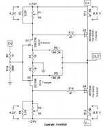
Ok Peter they are mounted soldier style now. What's the deal with the 10k vs 22k resistor deal? I've been installing the values shown in the schematic that was included (appears to be same as the Nelson Pass F-5 article on first watt) with the boards. Ive seen the feedback mod, but this appears to be
something that replaces the 10k resistors with 22K....can anyone explain this to me? I'm inclined to build per schematic, unless there appears to be a good reason for switching them.
Thanks,
Russellc
10K are part of current limiting circuitry and I simply don't use them; sounds better too, as reported by many others.
Ok Peter they are mounted soldier style now. What's the deal with the 10k vs 22k resistor deal? I've been installing the values shown in the schematic that was included (appears to be same as the Nelson Pass F-5 article on first watt) with the boards. Ive seen the feedback mod, but this appears to be
something that replaces the 10k resistors with 22K....can anyone explain this to me? I'm inclined to build per schematic, unless there appears to be a good reason for switching them.
Thanks,
Russellc
Hi,
Nelson Pass has said that 22K sounds better than the 10K, but both will work. Or, you can take your chances and build it without the protection portion of the circuit.
Hi,
Nelson Pass has said that 22K sounds better than the 10K, but both will work. Or, you can take your chances and build it without the protection portion of the circuit.
This is different than the feedback mod, right?
Only these two are changed? I noticed one BOM listed those as being spec'd as between 10k-22k,
I must have missed this (I am still reading the F-5 thread, mid 300s page wise...) or maybe havent got to it yet. Can anyone link this?
Thanks in advance for any assistance,
Russellc
Last edited:
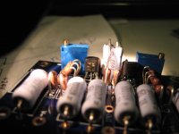
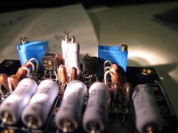
Another question from an inexperienced F-5 builder. This one concerns proper orientation of Q1,Q2 Q5 and Q6. The boards have little shapes drawn on that should result in proper orientation, (curved on one side, flat on the other, just like the components) but I have Q2 2SJ74 for 2sJ108, Q1 2SK170 for 2SK370. I didnt know if their pin outs were the same, I assume so, but would really like someone to tell me if this is proper orientation. Pic 1 and 2 show these devices in the orientation I thought was correct.
Similarly,Q5 and Q6 are the standard part, ZTX550 and ZTX450, again, the shape of the component matched the shape of the outline drawn on the board. but just in case, I'd like confirmation from someone who knows before I solder them in place.
Thanks to all you more experienced Pass builders,
Russellc
Attachments
Last edited:
I actually designed the board for 2SJ74 and 2Sk170.
ZTX devices should also be placed according to footprint outline.
ZTX devices should also be placed according to footprint outline.
On Pete's board, insert your ZTX NPN and PNP transistors as shown on the board.
On the Cviller board you need to reverse your ZTX components from the drawing on the board. The Cviller boards were drawn for BC components.
On the Cviller board you need to reverse your ZTX components from the drawing on the board. The Cviller boards were drawn for BC components.
This is different than the feedback mod, right?
Only these two are changed? I noticed one BOM listed those as being spec'd as between 10k-22k,
I must have missed this (I am still reading the F-5 thread, mid 300s page wise...) or maybe havent got to it yet. Can anyone link this?
Thanks in advance for any assistance,
Russellc
Yes, this is not refering to the feedback (R5&R6=50R, R7&R8 leave out; or R5-R8=100R). R1&R2 are also part of the feedback.
The 10K-22K is for R21&R22, which is part of the circuit protection (as in if you accidentally short your speaker wires). Here is a simplified schematic without the thermal tracking (R15&Th1) and circuit protection.
Attachments
Tech-DIY parts on Daniels board & my screw up
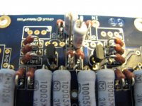
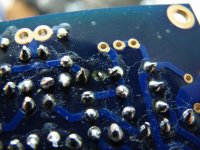
Thank you Alazira, Vdi_nenna and Peter Daniel for your time, patience and explanations. I have the boards done now, (pic below, and using the Tech-DIY parts kit) but when almost done with the second board, made a mistake. While my protocal is to double check the part and location, then again just before soldering. As I was preparing to
solder Q2, I got distracted, picked up ZTX450 and soldered it into Q2 location. Yes, all 3 legs before I noticed.
Well, taking the utmost time and care to not over heat the ZTX450, I was able to carefully remove most of the solder and get the ZTX450 free and soldered where it was supposed to go. I was careful and think the unit is ok. However...
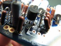
when I went to solder 2SJ74 into Q2 location a problem made itself obvious. I soldered the left most leg, let cool, soldered the center leg, let it cool. When I was soldering the rightmost leg, I noticed the solder wasnt wanting to puddle around the pad, so removed heat and inspected. It appears the little circular pad either melted, or was somehow vaporized or fell off. (see pic) Solder had run down the leg into the wire hole, which appears to be plated through. Also I flowed a little tiny bit more down the leg, allowed to cool, then flipped the board over and quickly put just a touch on the topside pad. (see pic of this also) Should I consider the board saved, or should I build another? I suppose the only way to test it is to flip the switch upon completion? Here's the pics: Sorry, the last one should have been second, showing pad damage.
Once before repairing a JBL 6230, a similar problem occurred with a small cap. I had to solder a small piece of wire in the hole, and then the cap's leg to that to get the circuit trace right. Least ways it didnt have the pots on yet, they were missing.😡
Thank you Alazira, Vdi_nenna and Peter Daniel for your time, patience and explanations. I have the boards done now, (pic below, and using the Tech-DIY parts kit) but when almost done with the second board, made a mistake. While my protocal is to double check the part and location, then again just before soldering. As I was preparing to
solder Q2, I got distracted, picked up ZTX450 and soldered it into Q2 location. Yes, all 3 legs before I noticed.
Well, taking the utmost time and care to not over heat the ZTX450, I was able to carefully remove most of the solder and get the ZTX450 free and soldered where it was supposed to go. I was careful and think the unit is ok. However...
when I went to solder 2SJ74 into Q2 location a problem made itself obvious. I soldered the left most leg, let cool, soldered the center leg, let it cool. When I was soldering the rightmost leg, I noticed the solder wasnt wanting to puddle around the pad, so removed heat and inspected. It appears the little circular pad either melted, or was somehow vaporized or fell off. (see pic) Solder had run down the leg into the wire hole, which appears to be plated through. Also I flowed a little tiny bit more down the leg, allowed to cool, then flipped the board over and quickly put just a touch on the topside pad. (see pic of this also) Should I consider the board saved, or should I build another? I suppose the only way to test it is to flip the switch upon completion? Here's the pics: Sorry, the last one should have been second, showing pad damage.
Once before repairing a JBL 6230, a similar problem occurred with a small cap. I had to solder a small piece of wire in the hole, and then the cap's leg to that to get the circuit trace right. Least ways it didnt have the pots on yet, they were missing.😡
Attachments

Last edited:
Regarding your 2SJ74 trouble, it's not only a pad damage but also a trace missing (pad connection with the rest of the traces). It's not a big deal, just use piece of wire to bridge it (check with the good board how it connects).
Regarding your 2SJ74 trouble, it's not only a pad damage but also a trace missing (pad connection with the rest of the traces). It's not a big deal, just use piece of wire to bridge it (check with the good board how it connects).
Looking at the circuit board loaded I cant tell. looking at the schematic it appears it just goes over to R4. I should (if this is correct) just wire and solder together the "problem" leg over to the exposed wire of R4?
The resistor in thr picture and the leg of Q2 nearest it? Or am I way off and should just stuff a new board?
Thanks Peter,
Russellc
Attachments

Last edited:

- Status
- Not open for further replies.
- Home
- Group Buys
- F5 pcb group buy...