Imho, 10ga is serious overkill.
I think 14ga is quite sufficient.
12ga would be nice.
10 ga is heavy duty if you need to minimize DCR for some reason...
All you need is wire and a way to make it go round and round on a bobbin or spool, etc...
There is no reason not to use an "iron core" to reduce the number of turns and maximize the inductance, imo. You just have to size the lams to meet the VA required for the job.
It is reasonable to use the secondary or primary of a suitable transformer for this...
_-_-bear
Well, I have a couple of lathes that can run at slow speed - ideal for winding I would say. However, its laying hands on the copper for almost no $$ is the problem!!
I do have a big microwave oven transformer though that might just do the trick.... further investigation required 🙂
Fran
I do have a big microwave oven transformer though that might just do the trick.... further investigation required 🙂
Fran
Scramble wound doesn't look pretty, and isn't quite as many mh per turns as "perfect lay" but works fine and you can do it on a lathe with hand held feed. Watch your fingers, wear tight fitting clothes. The lathe has no brains and no mercy.
_-_-
_-_-
Member
Joined 2009
Paid Member
Though i have not yet experimented it, i am quite shure that a capacitance multiplier could be a more elegant and a lot cheaper way to improve noise figure in a classA amplifier PSU.
That's what I think, it promises huge noise reductions and channel-to-channel isolation. But with FETs you get the 4V drop and with BJTs you need a driver device to handle the base current of the pass transistor. And you need a heatsink with mounting hardware, and the devices can fail. You do get the bonus option of zener regulation to the base, or a triac on the base to shut down the rails if there's a fault condition detected.
But the CLC offers a rather simple solution and need not be expensive if you accept the use of a common mode choke. Check out Digikey. I found a 4A choke with 6.9mH on tap for around $5 [PLK1332-ND].
Attachments
That's a cool choke, and inexpensive.
However, it's supposed to be used in the AC line.

Maximum current is specified as 4A RMS.
Any ideas on how it will behave in a typical F5 CLC (CLCLC) PSU?
However, it's supposed to be used in the AC line.
Maximum current is specified as 4A RMS.
Any ideas on how it will behave in a typical F5 CLC (CLCLC) PSU?
Member
Joined 2009
Paid Member
I figure the choke doesn't know which side of the trafo you put it on, but I assume the current limit is mostly a thermal issue - if you don't overheat it then it doesn't matter what the waveform going through it looks like.
I haven't a clue how it would work for the F5 but there are many other nice looking chokes in the digikey catalogue if this one isn't suitable.
I'm still liking the look of the Cap Multiplier as a technically better option but with the choke there appears to be less to understand and so fewer possible complications. For some amplifiers, the turn-on thump is a deal-killer without a cap multiplier to slow things down.
Last edited:
It's been 4 weeks ...................... 😀
🙂. my 2nd child should be popping out in the next couple of weeks. we made a decision to get rid of my dedicated hi-fi room soon than later, and i've been kicked down into the office in the man-cave. i'm in the middle of building a USB DAC - space is at a premium now and i've decided to pack away the CDs for a hard drive. although i did finish populating my F5 boards tonight.
I'm in the middle of assembling a F5 with a CLC PS.
I bought my chokes from Automatic Electric Europe
They are rated 10mH, 5A DC, 0.0695 Ohm, size: 80x70x60mm
The price was 26€ for a choke.
The nice thing about them is the low DC resistance, it's almost impossible to make an air choke with the same specs or it will be enormous.

I bought my chokes from Automatic Electric Europe
They are rated 10mH, 5A DC, 0.0695 Ohm, size: 80x70x60mm
The price was 26€ for a choke.
The nice thing about them is the low DC resistance, it's almost impossible to make an air choke with the same specs or it will be enormous.
Last edited:
I'm in the middle of assembling a F5 with a CLC PS.
.....
can you give us dimensions ?
dim. of lams , air gap , wire dia ?
it's always handy to have recipe
Quick, kinda OT question:
I plan on cutting open a large microwave oven transformer to make the chokes. Whats the best way to get the laminations apart? Do I just cut the welded seams and then it comes apart?
Fran
I plan on cutting open a large microwave oven transformer to make the chokes. Whats the best way to get the laminations apart? Do I just cut the welded seams and then it comes apart?
Fran
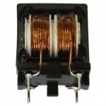
Hi Choky,
the diameter of the wire is about 1,65mm (14AWG)
The iron is an EI core,
outer dimensions seen from front like in picture: width: 65mm, height: 78mm, width outer lams: 13mm, depth lams: 28mm
so the outer lams are 13x28mm, I can't see the inner lams on which the wire is wound. But I'm guessing that it's 26 mm.
Attachments

Last edited:
Hi Choky,
the diameter of the wire is about 1,65mm (14AWG)
The iron is an EI core,
outer dimensions seen from front like in picture: width: 65mm, height: 78mm, width outer lams: 13mm, depth lams: 28mm
so the outer lams are 13x28mm, I can't see the inner lams on which the wire is wound. But I'm guessing that it's 26 mm.
tnx 😉
if core is standard EI , then tongue is 1/3 of overall width ....... in this case height
so 78/3 =26 mm ,as you wrote
edit :
I can't get - what's height of lam stack ?
Last edited:
Wow, good guessing of me
But I'm still having problems with the lottery numbers 🙂
You mean with height of lam stack: the depth of the stack like in picture, that's 28mm
But I'm still having problems with the lottery numbers 🙂
You mean with height of lam stack: the depth of the stack like in picture, that's 28mm
Last edited:
Hi
I just finish my F5 and connect it to system.
Soruce : Micro Seiki DD40 + ATOC3
Pre : Peereaux SM2
Loudspeakers: DIY (2 an1/2 way) 2 Vifa XT18WO + XT25
It sounds nice. A lot of details and wide sound scene. Bass very good controlled. A general impression is: "very polite".
I start with bias 1A (I use trafo with 4x22V secondary).
Can anybody tell me what will change in sound when I increase bias
ok, so I took apart the microwave oven transformer. I ended up with 58m (190 ft) of 1.4mm wire, which I think is about 15g... possibly a little small. From an online calculator, I would need this much wire for even one 2mH inductor - so I'm not going to have enough to replace the CRC with CLC.
What I might do is make up some smaller rated inductors, about 0.5mH each and use them after the CRC. I could use some nice nichicon muse caps on the end of the PSU.
For 0.5mH inductor, the air core should be 70mm, height is 18mm and 17m of 15g wire...... so this will be big diameter.
Its probably worth a try, but if anyone thinks what I'm doing is stupid, let me know!!
Fran
- Home
- Amplifiers
- Pass Labs
- F5 Listening Impressions & Discussion