
It looks like the Pass BA-3 boards from the diyaudio store would work for this F5 headamp...almost perfect.
Which brings up another question:
I have the BA-3 configured as a preamp now. I have tried it with a set of Grado SR125 (32 ohm). The sound was not so good. No drive at all.
Iam sure EVUL's F5 headlamp is great. Everything he makes is great. But why did the BA_3 front end not work well with my Grado's? Is it the output impedance set by that 332R resistor (too high) or the fact it is only biased at 100ma vs EVUL's higher bias?
Attachments
You need to add a driver stage like e.g.
And then you'll be OK with a BA3.
I am also in the middle of a new portable design with Zero Global Feedback but using IC's.
It has a gain stage with ZGF followed by a follower driver stage, using 2x 9V batteries.
It also has a cross feed buffer, all in a Hammond 1550B case.
When it is ready you'll know, but not before. 😉
Patrick
Thanks Patrick...well a no feedback, IC-based, battery-powered amp sounds more than interesting. Judging by the amount of C-moy based amps being made and sold out there you would probably have something desirable to a lot of people. I am new the headphone thing...and it seems like a lot of the headphone oriented gear is all about size and style and headphone users are more interested in digital sources and dacs and such. Big, hot class a amps and headphones seem to not make sense for a lot of headphone nerds. Maybe it's a space issue...
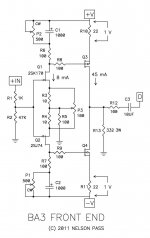
I appreciate you attaching the schematic. I did some detective work...found out it's the new Pass Diy headphone amp in the works. I will probably use it and if I like headphones move on to the DAO which looks amazing from a use of parts and engineering perspective.
I appreciate you attaching the schematic. I did some detective work...found out it's the new Pass Diy headphone amp in the works. I will probably use it and if I like headphones move on to the DAO which looks amazing from a use of parts and engineering perspective.
> Judging by the amount of C-moy based amps being made and sold out there you would probably have something desirable to a lot of people.
Until they see the Bill of Material and the price tag of the components.
But then you separate the men from the boys.
😉
Patrick
Until they see the Bill of Material and the price tag of the components.
But then you separate the men from the boys.
😉
Patrick
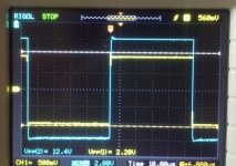
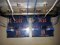
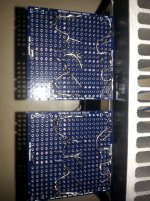
I built the F5 Headamp.
Adjusted the 5K Pot to minimum.
Connected one board to power supply, and 3.3R resistors heated too much.
Can someone identify what causes it from the pictures?
Adjusted the 5K Pot to minimum.
Connected one board to power supply, and 3.3R resistors heated too much.
Can someone identify what causes it from the pictures?
Attachments
The component values of the pdf you posted above is from post #1.
The circuit has evolved since.
The gate stoppers for example should be at least 1k instead of 100R, and the Beta tester is actually using 2k.
Also the later layouts have local power supply caps.
http://www.diyaudio.com/forums/pass-labs/271926-f5-headamp.html#post4277624
http://www.diyaudio.com/forums/pass-labs/271926-f5-headamp.html#post4277681
And if you adjusted 5k trimmer to minimum (= 0 ohm), then there should be no current in the 2nd stage.
Patrick
Last edited:
Awesome thread!
I would like to build one using 2sj44/2sk163. As Patrick described 5 years ago 2sk170/2sj74 have a quite different quadratic curve at the same Idss, P is going closer to Vgs axis... Correct me if I am wrong but to do that I need to find MOSFETs that don't need to be biased high to perform well like irf610/irf9610 and also with a lower Vgs(off) - something around 1.8-2V, yet still pretty much complementary? It would be also great if it would be possible to match P to N but not necessarily 🙂 Is anything like that around?
With 2sj44/2sk163 I would probably need to double jfet gate resistors as they have lower capacitance... to reduce bandwidth
> to do that I need to find MOSFETs that don't need to be biased high to perform well like irf610/irf9610 and also with a lower Vgs(off) - something around 1.8-2V,
Incorrect.
It depends on the Idss of your JFETs and the value of the drain resistor.
> With 2sj44/2sk163 I would probably need to double jfet gate resistors as they have lower capacitance...
Not necessary.
Patrick
Incorrect.
It depends on the Idss of your JFETs and the value of the drain resistor.
> With 2sj44/2sk163 I would probably need to double jfet gate resistors as they have lower capacitance...
Not necessary.
Patrick
Thank you Patrick.
Ok, I need to rethink it 🙂
By any chance has anyone spice models of NEC jfets? I can try Toshiba models changing Vto Beta Vg Cgs... but not sure how reliable it might be...
Ok, I need to rethink it 🙂
By any chance has anyone spice models of NEC jfets? I can try Toshiba models changing Vto Beta Vg Cgs... but not sure how reliable it might be...
.model 2sj44 PJF(Beta=20.62m Rs=1 Rd=1 Betatce=-.5 Lambda=1.5m Vto=-.75
+ Vtotc=-2.5m Cgd=17.79p M=.3333 Pb=1 Fc=.5 Cgs=32p Isr=174.9p
+ Nr=2 Is=17.49p N=1 Xti=3 Alpha=10u Vk=100 Kf=81.89E-18 Af=1)
*$
.model 2sk163 NJF(Beta=16.97m Rs=.3153 Rd=.3153 Betatce=-.5 Lambda=10m
+ Vto=-.75 Vtotc=-2.5m Cgd=13.34p M=.3333 Pb=1 Fc=.5 Cgs=9p
+ Isr=174.9p Nr=2 Is=17.49p N=1 Xti=3 Alpha=10u Vk=100 Kf=0 Af=1)
*$
No idea how accurate.
Patrick
Many years ago from a Japanese site which no longer exists.
Probably a DIY model, so I would not trust it to give you reality.
Patrick
Probably a DIY model, so I would not trust it to give you reality.
Patrick

New power supply? Well, regs indeed...
JC insipred, Patrick tweeked cap multiplers or somenthing totally new?
JC insipred, Patrick tweeked cap multiplers or somenthing totally new?
Not new, already in my own build.
Just new, more compact PCBs.
LM317 / 337 followed by Darlington cap multiplier.
Just something simple.
Patrick
Just new, more compact PCBs.
LM317 / 337 followed by Darlington cap multiplier.
Just something simple.
Patrick
Patrick,
What's the reason for such high value of the source degeneration resistors of the mosfets ? I remember that in the F5X you were aiming for a value of these components as low as possible.
I am planning to give a try for this project using the 2k2013/2sj313. I have a nice, but tight case for it, so most of the components will be SMD.
Thanks,
Davide
For F5X, 0R22 at 2A bias = 0.66V.
For F5HA, 3.3R at 150mA bias = 0.495V.
If you go and have a look at Wayne's opamp / follower headamp, he is using 10R at ~half the bias.
So 3.3R is actually on the low side.
Watch resistor dissipation when building SMD.
🙂
Patrick
For F5HA, 3.3R at 150mA bias = 0.495V.
If you go and have a look at Wayne's opamp / follower headamp, he is using 10R at ~half the bias.
So 3.3R is actually on the low side.
Watch resistor dissipation when building SMD.
🙂
Patrick
- Home
- Amplifiers
- Pass Labs
- F5 Headamp ?