> so this must be an impressive amp if it dethroned your Dynahi .....
That was not so difficult if you understand how to use FETs properly.
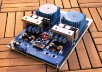
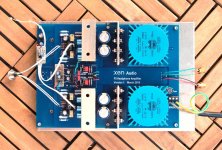
For once I am doing an all-in-one PCB.
Well, almost all-in-one .........
Patrick
All in one is nice for hp amps IMO, maybe off board Tx is a little more versatile.
Thanks Luke 🙂
Go for it!
will do, only my stuff aint pretty🙂 I think I need a CNC machine.
> All in one is nice for hp amps IMO, maybe off board Tx is a little more versatile.
You can saw off the right half of the PCB and connect e.g. batteries.
Connection hole provided.
Patrick
You can saw off the right half of the PCB and connect e.g. batteries.
Connection hole provided.
Patrick
I have a number of PM's asking for PCBs for the F5-HA.
We'll only make the PCB available :
1) when I have time to test and prove that it is error free;
2) there are sufficient interest to make it worthwhile for the trouble;
3) Nelson has no objections.
Those who know us know that we have little or no time to baby sit every build.
So if you are not an experienced builder who understands what you are doing, then this is most certain not the right project for you.
But many thanks for your interest in any case,
Patrick
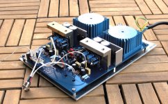
It is not the best weather for photography today. But here is an update.
Volume control pending, and not yet tested, and the regulators are temporary solution ......
Still need a few more days.
Patrick
.
Volume control pending, and not yet tested, and the regulators are temporary solution ......
Still need a few more days.
Patrick
.
Attachments

Last edited:
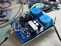
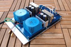
First sound today (this one with Fairchild MOSFETs).
All worked first time, except one small layout error which was discovered before testing. (luckily......)
Simple rectification, and all worked fine.
It does not even affect anyone else than those (like me) using LDR volume.
A slight modification was also added to address a 1dB hump on the frequency response while using passive pot at -6dB.
A simple 47p mica cap was added in parallel with the input resistor to Gnd.
Flat response to 500kHz and above, depending on volume setting.
DC offset within +/-5mV.
Just case and cross-feed buffer to add.
😉
Patrick
.
Attachments
mistakes can happen
In one case I carefully wired up one of the DMOS pass elements and saw unregulated output voltage on turn-on. Fortunately I was bringing up each section independently and nothing was connected to the output.
It turned out I stuck an NMOS device in where a PMOS was supposed to be, and of course the body diode conducted. No harm done. With the removal and exchange for the correct part, all was well.
I've been breadboarding high-performance series regulators for a phono preamp. The construction is hand-wiring with bus wire and teflon tubing where needed, on Twin ground-plane pad-per-hole protoboards.All worked first time, except one small layout error which was discovered before testing. (luckily......)
Simple rectification, and all worked fine.
It does not even affect anyone else than those (like me) using LDR volume.
😉
Patrick
In one case I carefully wired up one of the DMOS pass elements and saw unregulated output voltage on turn-on. Fortunately I was bringing up each section independently and nothing was connected to the output.
It turned out I stuck an NMOS device in where a PMOS was supposed to be, and of course the body diode conducted. No harm done. With the removal and exchange for the correct part, all was well.
It was just a careless mistake that I swapped positive & negative rails for an auxiliary 9V supply for the LDR current source.
Luckily spotted it before power on, so turned the caps the right way round, and replaced 78L09 with 79L09.
Problem solved. 🙂
Patrick
Luckily spotted it before power on, so turned the caps the right way round, and replaced 78L09 with 79L09.
Problem solved. 🙂
Patrick
Not to go too off-topic, but it is interesting, when one is putting something together, that we may notice something that eluded us in the design phase. I just had that happen as I was continuing the breadboarding of a preamp. I realized that I might not have fully considered the power cycling transients, and so stopped building in order to revisit the simulations.
I had indeed overlooked the possibility of certain bipolars sustaining reverse base-emitter voltages on power down. Since the configurations involved base-current-recycling techniques, a la Boxall and his successors, and normally had only several tenths of a volt across the auxiliary transistor, it was easy to suppose that things were secure. But the bias voltages are bypassed by capacitors to reduce voltage divider noise, and upon the decay of the rail voltages can induce significant reverse base-emitter voltages for a moment.
Since bipolars typically break down around 6V reverse, and since these breakdown events cause an increase in noise, which is cumulative, it is well to prevent it. And my simulator does not take note of the breakdown voltage. The protection is to have a small-signal diode across the particular B-E junction.
Ramping the rails slowly may also be a fix, but it is nice to have an additional level of protection.
Someone asked about a balanced version .......... !!!!
Well, it already exist. Just need some slight modification on the feedback network :
http://www.diyaudio.com/forums/pass-labs/225230-f5x-preamp-4.html#post4281250
It is then a truly balanced circuit, designed as such, with a Curl differential JFET input stage.
Not just two single-ended circuit running in positive and negative phase.
(Compare an OPA1632 to an OPA1642.)
Patrick
Last edited:
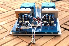
All sub-modules soldered and system tested fully functional today.
(Input / output / power cabling provisional, awaiting enclosure.)
The modified Linkwitz cross-feed buffer adds a realistic stereo image and for me at least it is definitely here to stay.
Very precise image, as one would expect from dual mono construction.
Really great sound for such simplicity, but you knew that already. 🙂
Patrick
.
Attachments
Next step is Beta test.
I already have a candidate. But he needs a few months.
With luck then in time for Xmas.
🙂
Patrick
I already have a candidate. But he needs a few months.
With luck then in time for Xmas.
🙂
Patrick
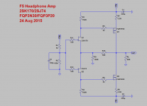
Someone requested an updated schematics for his Vero board build.
You should appreciate that it is still work in progress, there are many variations possible, .... So there is no definitive / final version.
And I cannot possibly keep posting every evolution I make along the way with proper documentation.
But I'll post one here which represents the one in post #277.
Drain resistor values depend of course on FET Idss and Vgs.
When the PCB is made available later, it will be accompanied by proper documentation.
These include, amongst others, a detailed circuit description.
Thanks you for your interest,
Patrick
.
Attachments
- Home
- Amplifiers
- Pass Labs
- F5 Headamp ?