I've been asked again about voltage and current limits, further to :
http://www.diyaudio.com/forums/pass-labs/271926-f5-headamp-3.html#post4338647
The JFETs are specified at 24V, so naturally you should not go beyond that, unless you wish to use higher voltage JFETs (they exist).
Then the next limit is dissipation on the MOSFETs.
Assuming you have a heat sink large enough and is dimensioned at 55°C, you can go to about 7W per MOSFET maximum.
That means 290mA at 24V, 350mA at 20V, 390mA at 18V, ...., etc.
The next is the MOSFET source resistor.
Assuming you use 2W as I do, maximum current is 390mA to retain a design margin of 4.
And then there are limits with my PCB if you do not Vero build :
The transformers are 25VA per channel, before rectifiers.
That means roughly 17.5VA after regulators.
For Class A, due to the high ripple currents, you should at least have a factor of 2.5 margin.
That gives you 7VA; or +/-15V 230mA, +/-18V 190mA, ....., etc.
The original +/-15V 150mA is not far from max.
You should then watch dissipation of the regulators.
Maybe you need to mount them directly on the heat sinks and then run long wires to the PCB.
If you want tons and tons of power to drive e.g. a Hifiman HE1000, I suggest you just use a F5 power amp.
PCBs available at forum store.
Patrick
Can you use an external PSU (incl. regulators) with my PCB ?
Yes, it is designed to do so, and you may even use batteries.
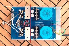
You can cut the PCB along the red line shown.
Additional holes are provided for mechanical mounting, as well as 8 solder pads for +Vs / Gnd / -Vs connections.
You can still retain the Cross Feed Buffer in so doing.
The MOSFETs are bolted onto the bottom plate.
Any solid aluminium plate of 3mm or more will have no problems conducting the heat to the heat sinks.
You need to use thermal grease or foils between the two, without saying.
Patrick
.
Yes, it is designed to do so, and you may even use batteries.
You can cut the PCB along the red line shown.
Additional holes are provided for mechanical mounting, as well as 8 solder pads for +Vs / Gnd / -Vs connections.
You can still retain the Cross Feed Buffer in so doing.
The MOSFETs are bolted onto the bottom plate.
Any solid aluminium plate of 3mm or more will have no problems conducting the heat to the heat sinks.
You need to use thermal grease or foils between the two, without saying.
Patrick
.
Attachments
Last edited:
I've been asked again about voltage and current
If you want tons and tons of power to drive e.g. a Hifiman HE1000, I suggest you just use a F5 power amp.
PCBs available at forum store.
Patrick
Hello Patrick. I have some headphone very hard. Is better make a F5 directly?
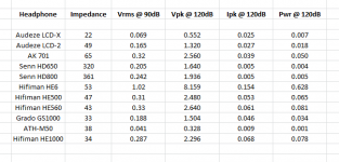
Attached is a table of the power hungry headphones I know of.
The standard F5-HA will drive all of them to 120dB SPL in pure Class A, with less than 0,1% THD, in most cases around 0.01%.
So I leave you to decide for yourself whether you still want more power.
Patrick
.
The standard F5-HA will drive all of them to 120dB SPL in pure Class A, with less than 0,1% THD, in most cases around 0.01%.
So I leave you to decide for yourself whether you still want more power.
Patrick
.
Attachments
Very nice design Euvl. Thank You for sharing.
The most interesting part (for me) is the cross feed network.
There are two ways to build it.
1. After the headamp:
Headphone xfeed
2. Before the amplifier (line level):
Modified Linkwitz Crossfeed
schematic:
http://tangentsoft.net/audio/misc/mlxfeed-sch.pdf
We prefer the option two.
B1 buffer - cross-feed - headamp.
EUVL, what is the frequency response of your cross-feed circuit?
We do not use a passive cross feed at the headphone after the amplifier.
This is because not every headphone has a flat impedance over the audio band.
And the voice coil of the phone is reactive, not a pure resistor.
So we use line level, but different to what you proposed above.
We assume that the signal source is low impedance (~100R) and (mostly) resistive.
This can be used to drive a high impedance (~10k), passive cross feed filter (whether Meier, modified Linkwitz, Danyuk, or else.)
The output of the passive filter is then buffered by a JFET source follower which in turn drives the volume control pot.
The pot then drives the F5-HA directly, without the need of an additional buffer.
The passive cross feed filter is passive, so its frequency response is as determined by the passive network.
The output impedance of the filter in conjunction with the input capacitance of the JFET follower limits the frequency response of the follower.
For our own build, we used 2SK117, which is one of the lowest capacitance JFET available with decent Yfs.
So bandwidth is no issue.
You may of course also use BF862, which is proven to be low noise, low capacitance, and still widely available.
There is also the SMD equivalent of 2SK117, namely 2SK209, also widely available..
Patrick
Last edited:
I should add that another reason of putting the cross feed before the volume pot is to keep the full signal at the cross feed for maximum dynamic range.
Patrick
Patrick
Attached is a table of the power hungry headphones I know of.
The standard F5-HA will drive all of them to 120dB SPL in pure Class A, with less than 0,1% THD, in most cases around 0.01%.
So I leave you to decide for yourself whether you still want more power.
Patrick
.
Thanks Patrick. 😉
Comparison of frequency responses of different Cross Feed filters :
http://www.diyaudio.com/forums/head...ss-zgf-headphone-amplifier-4.html#post4436996
Patrick
http://www.diyaudio.com/forums/head...ss-zgf-headphone-amplifier-4.html#post4436996
Patrick
Another question -- so many !!!!!!
Can we use the F5-HA as a transconductance amplifier and drive the headphones in current mode (as in Bakoon HPA-21) ?
Of course we can.
You simply put a current sensing resistor between Load and Gnd, and tie that connection to the feedback node of the input stage.
The current gain is then approximately 1/R_sense.
R_sense wants to be a low-distortion metal film resistor with sufficient wattage to avoid thermal distortion.
You also need to adjust its value according to your headphone.
I suggest 0.05~0.10x of your phone impedance.
Distortion and frequency are as good, but it depends of course on how flat the load impedance is.
Zout is about 17k as shown in the schematics.
Patrick
Attachments
A typing error in the asc file (title comments).
Current Gain should be 0.28S, not 2.8.
Sorry for that,
Patrick
Current Gain should be 0.28S, not 2.8.
Sorry for that,
Patrick
Thanks.
But if you know what EUVL means (engineering wise) then this is kindergarten.
😉
Patrick
But if you know what EUVL means (engineering wise) then this is kindergarten.
😉
Patrick
Well, my proto on PCB is already built and working.
Stixx have been listening to the original Vero Build all the time.
The Beta-Tester has all the parts he needs, just needs time to build.
Meanwhile, I am building a second one .....
So it has not stopped, but there is nothing totally new to report.
The Beta-Tester will start a new Build-Thread once he has progress.
Patrick
Be patient.
Needs time to tidy up things and get rid of any mistakes before you can start.
Patrick
Needs time to tidy up things and get rid of any mistakes before you can start.
Patrick
A PM asked for advise of adjustment for the F5-HA.
As in the F5 power amp, first thing to adjust are bias and DC offset.
The bias can be measured across the 3.3R power resistor.
And you can start with 150mA (so about 0.5V).
Then set DC at the output to zero, and readjust after 30 minutes or so.
The rest is the same in any DIY amp -- square wave, frequency response, distortion, .... etc.
Patrick
- Home
- Amplifiers
- Pass Labs
- F5 Headamp ?