So all resistors, except R13 and R14, seems to be wrong...
lol I might as well start with a brand new board... thanks a lot for confirming
Cheers
KJ
lol I might as well start with a brand new board... thanks a lot for confirming
Cheers
KJ
If you were able to de-solder the transistors, surely you can de-solder the resistors. You've got a solder sucker right.
When you put things back together, solder your resistors from the top side of the board. Use a tooth pick or something as a spacer to keep them off the board.
Get some Keratherm insulators from the store so you don't have to mess with that goop when taking the boards in an out.
You should re-solder and trim those thermistors also.
If you were able to de-solder the transistors, surely you can de-solder the resistors. You've got a solder sucker right.
.
Lol, yes I do have a solder sucker ... but if you look at my last pictures, only 1 transistor of the bunch was really desoldered, I cut off the leads of the others at half height and resoldered them... that 1 transistor was a pain to get out without damaging the board... I really don't like - or more accurately lack the skill - to desolder things, it always ends up messy 😀
Best regards,
kj
My electronics teacher in high school showed me the best way to de-solder without damaging the board. Hold the board about a foot off the table, warm up the solder and drop the board. Knocks most of the solder right off.
Lol, yes I do have a solder sucker ... but if you look at my last pictures, only 1 transistor of the bunch was really desoldered, I cut off the leads of the others at half height and resoldered them... that 1 transistor was a pain to get out without damaging the board... I really don't like - or more accurately lack the skill - to desolder things, it always ends up messy 😀
Best regards,
kj
Desoldering can be a PITA, if it's not going well right away with the solder sucker I usually add more solder and then try again. It looks like not having enough solder to be sucked in does not work best..or maybe my desoldering pump is getting old...LOL
BR,
Eric
Hold the board about a foot off the table, warm up the solder and drop the board.
😱😱
Lol, yes I do have a solder sucker ... but if you look at my last pictures, only 1 transistor of the bunch was really desoldered, I cut off the leads of the others at half height and resoldered them... that 1 transistor was a pain to get out without damaging the board... I really don't like - or more accurately lack the skill - to desolder things, it always ends up messy 😀
Best regards,
kj
Yes, you would cut the leads close to the body of the resistor. heat it up and then quickly grab it with a needle nose and pull it out. Now get a very fine tip for your soldering station. push it right into the hole and suck the solder out from the other side.
Attachments
I use soldering wick for all projects - where desoldering is needed ...
Removal of Solder Using Solder Wick
•
Removal of Solder Using Solder Wick
•
If all you need is to open up the hole to put in another component, sometimes it is easiest to just melt the solder and insert a round toothpick. Then twist it out in a couple of seconds, leaving a round hole.
Hi Guys,
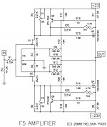
I am happy to report that after using the right schematic and parts (attached below for beginners like me 😀), it all went smoothly. The bias setting went ok too. I just closed it up, put the cover on it at 0.5v and 0.3mv offset. I will check on in a hour or so 🙂
Cheers
KJ
P.S. Matched fets (i.e. 2SK170 and 2SJ74) are not in the parts list.
Attachments
Thanks Kevin. I am very happy. This is being my very first amplifier build.
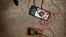
Ok, it's been an hour or so. The offset went up to 6mv...is that normal/acceptable?
I played with P1 and P2 again to lower it a bit...after I have put the cover it started to go up again. It's now at 1.3mv. R7 and R8 are stable at 0.59v
What do you think?
Edit: I have been staring at the meters for the last 10 minutes 🙂 and the voltage across the output resistors is stable one at 0.59v and one at 0.6v. Offset is going up and down from 1.5mv to 2mv
KJ
Last edited:
As far as I can tell that's an acceptable range.
If it were me it would be hooked up and playing music.
If it were me it would be hooked up and playing music.
Thanks Eric. Kevin, I am dying to hook it up and test it...but it's getting late 🙂 ....tomorrow 😉
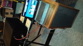
Ok, so I hooked up the one channel I built so far and tested it for close to 2 hours and it worked perfectly and sounded very good. I measured the temp of the mosfets just before I shut the amplifier down and they were 39-40c, so 17 degrees above ambient temp so we're good 😎
Now, on to the other channel...
Cheers
KJ
Now, on to the other channel...
Cheers
KJ
Attachments
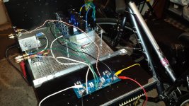
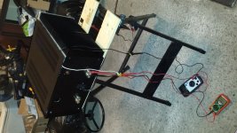
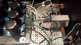
Well the 2nd board did not go well. The bulb stays on... what does it mean? a short? or could it be that I am not wiring the boards properly. Here is a picture of how it is now. I started with only 1 green wire going from the PS board to safety earth through the CL-60. Before I connect the 2nd board, the bulb used to go off very quickly. How long can I afford to wait before I do serious damage? 😱
Any help is much appreciated... thanks
KJ
Any help is much appreciated... thanks
KJ
Attachments
- Status
- Not open for further replies.
- Home
- Amplifiers
- Pass Labs
- F5 build power on with smoke from R19 and R20