Delays
The best of plans...
The USPS was nice enough to lose my last Mouser delivery. Mouser was very kind and is resending it free of charge, but the loss is the reason for the delay in etching new boards.
The time has allowed me to complete my OB speaker baffles. When McMaster brings the Tee-nuts, I'll have my FF85Ks over Alpha 15s. The baffle design is nice, it allows me to modify the standard build to a U-baffle if desired in a few seconds.
I also received my 68,000uF 75V caps - awesome beasts.
For now - awaiting UPS (no more USPS).
are they the new kemets? they have some new very high voltage large caps going right up to almost 1000000uf
The best of plans...
The time has allowed me to complete my OB speaker baffles. When McMaster brings the Tee-nuts, I'll have my FF85Ks over Alpha 15s. The baffle design is nice, it allows me to modify the standard build to a U-baffle if desired in a few seconds.
I think FF85K with Alpha 15 should be quite nice.
For very little extra effort and money I am confident you will be more than pleased with the result (just my gut feeling).
those caps are avaiable from Uriah (udailey). I got six too and they are awesome.
what brand ?
It's very close.
My day job got super busy, the USPS misplaced some parts, and the build just got slower than I'd hoped, but...
Below are pics of:
My day job got super busy, the USPS misplaced some parts, and the build just got slower than I'd hoped, but...
Below are pics of:
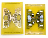
- The finished PCBs for the Balanced-Cascoded F5
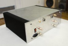
- The back of the case I'm using
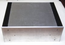
- The front of the case I'm using
- The innards - four 68000uF caps, MUR3020 diodes, two different sized NTCs (the big one is just for fun), my 800VA 12V toroid (good to 1000VA), and my Toshiba MOSFETs mounted to the Conrad heat sinks.
Attachments

ur much better off with the caps as close together as possible.
I'm waiting for the cap mounts, I've been thinking of putting them sideways with their bases attached to the front plate. The only other idea I had was some sort of jig to hold them together - keeping the front plate clear as a heat sink for the diodes and chassis resistors.
My day job got super busy, the USPS misplaced some parts, and the build just got slower than I'd hoped, but...
Below are pics of:I'm using 2SK1530 and 2SJ201 and I'm getting 20 pair of Toshiba 2SK3497/2SJ618 to try too. I hope to jury rig it togther this weekend.
- The finished PCBs for the Balanced-Cascoded F5
- The back of the case I'm using
- The front of the case I'm using
- The innards - four 68000uF caps, MUR3020 diodes, two different sized NTCs (the big one is just for fun), my 800VA 12V toroid (good to 1000VA), and my Toshiba MOSFETs mounted to the Conrad heat sinks.
I forgot to mention, I ultimately went with a voltage divider that sets the base of the cascode transistor to 11.5V (10K ohm and 22.1K ohm resistors with 16.785V rails). That's as good a starting point as any. It's easy enough to change lower or higher once I'm up and running.
With the external metal case of each cap being at 'ground,' one can arrange them to 'shield' (or 'deflect') electric fields (although not magnetic fields) from rectifiers and transformers. But that is probably a more theoretical (or visual) improvement than a measurable one, and I'd like to hear other opinions on this...?
I have read on diyaudio forums that placing caps on their side is um, not so good...
I have read on diyaudio forums that placing caps on their side is um, not so good...
Last edited:
With the external metal case of each cap being at 'ground,' one can arrange them to 'shield' (or 'deflect') electric fields (although not magnetic fields) from rectifiers and transformers. But that is probably a more theoretical (or visual) improvement than a measurable one, and I'd like to hear other opinions on this...?
I have read on diyaudio forums that placing caps on their side is um, not so good...
These caps won't fit upright. I have smaller ones, but I was hoping to use these (68000uF each). While it's rare, I have seen a few pics of folks mounting caps sideways. My search of the forum did not yield results on the issue, can you point me in the right direction?
I have read on diyaudio forums that placing caps on their side is um, not so good...
snap mount for print mounting should be ok
but regarding the big screw mount caps I have seen/read manufactor advise against mounting 'bottom up'
btw, I also found that the bottom screw stud mount is intended for added cooling
heck, there's always something new to learn about
'Sakis' said this about an Acurus amp that had caps on their side:
"i presume that you understand why i dont like big caps placed like that ..... ( fluids go to only one side through the years and then you get less capacitance )"
That's all I've ever heard. Sakis ought to know. Use what you have: I'm inclined to make a compromise if necessary.
"i presume that you understand why i dont like big caps placed like that ..... ( fluids go to only one side through the years and then you get less capacitance )"
That's all I've ever heard. Sakis ought to know. Use what you have: I'm inclined to make a compromise if necessary.
snap mount for print mounting should be ok
but regarding the big screw mount caps I have seen/read manufactor advise against mounting 'bottom up'
btw, I also found that the bottom screw stud mount is intended for added cooling
heck, there's always something new to learn about
I would put them on their side, not upside down. The real issue is I bought these for a song ($10 each). If I need to replace a year earlier because of side mounting, I can spend the extra $10 each.
None the less, I'll start by testing with my standard F5 caps which are 8*18000uF.
I would put them on their side, not upside down.
same thing 😉
whatever, probably just a industrial safety standard for the toughest conditions
to avoid possible contamination spill on other vital curcuits
you know, these things are used in power plants, wind mills etc
its that little rubber plug that comes out if pressure gets too high
prevents it from blowing
I doubt its any issue here
though, knowing that there might be some air inside the can, I do understand the possible issue when positioned horisontal
anyway, I prefer easy access to the cap screws
same thing 😉
whatever, probably just a industrial safety standard
Safety - who needs safety, we're talking Class A!
Seriously though, I'll use my smaller caps until I can figure out a good way to mount the big boys. I snagged eight 4.5"x7"x4" heat sinks which will fit the big caps when converted to a case.
I mounted and wired the power system last night. 800VA toroid to 8*MSRF1560s to 8*18000uF caps. I got 16.5V at the rails - as expected.
I also mounted the channel PCBs. All that's left is wiring from the PS to the PCBs and PCBs to XLR/RCAs. Normally this would take one more night, but we're busy tonight, so I'd guess this runs into 2-3 days to finish. This is just the temporary set up, if it goes well, I'll wire something neater and cleaner as the final version.
Finally, I just heard I'll be getting my 20 pairs of Toshiba 2SK3497/2SJ618 in the next few days. More F5 variants on the way!
Those 68,000uF caps are really overkill for the F5. The key rating for those caps is the voltage. 68,000uF @ 75 VDC. That's a rare combination and that's what makes them attractive at the price.
I've also read that caps should be used at 80% of their voltage rating. Using them at much lower voltages causes polarity reversal. Don't hold me on this, but I did read it here.
Anyway, using the exact supply from the F5 article should be plenty fine. No need to go bananas here.
I've also read that caps should be used at 80% of their voltage rating. Using them at much lower voltages causes polarity reversal. Don't hold me on this, but I did read it here.
Anyway, using the exact supply from the F5 article should be plenty fine. No need to go bananas here.
- Status
- Not open for further replies.
- Home
- Amplifiers
- Pass Labs
- F5 Amps - Building a Quartet of Amps in search of the Ultimate F5