Choky
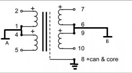
I looked at the data sheet and believe on the input side the two primary windings should be hooked up in parallel. ( 2 and 4 connected ; 1 and 5 connected.) positive phase connected to 2/4 and negative phase to 1/5.
Alternately 1 and 4 could be grounded and positive connected to 2 and negative to 5.
On the secondary side the center taps (6,9) should be grounded as you mention in previous post and plus output connected to 7 and negative phase to 10.
With a gain of 4x the 2V RMS from DAC should be raised to 8V
Thanks
what sort of signal you are using ?
ballanced ,symmetric , non-ballanced ?
if you use primaries connected in series , with CT grounded at signal side , and secondaries in series - with their CT connected to gnd at receiving side .......... you'll have both perfect symmetric balanced ........ and gain of 2:8
😉
ballanced ,symmetric , non-ballanced ?
if you use primaries connected in series , with CT grounded at signal side , and secondaries in series - with their CT connected to gnd at receiving side .......... you'll have both perfect symmetric balanced ........ and gain of 2:8
😉
Choky
I looked at the data sheet and believe on the input side the two primary windings should be hooked up in parallel. ( 2 and 4 connected ; 1 and 5 connected.) positive phase connected to 2/4 and negative phase to 1/5.
Alternately 1 and 4 could be grounded and positive connected to 2 and negative to 5.
On the secondary side the center taps (6,9) should be grounded as you mention in previous post and plus output connected to 7 and negative phase to 10.
With a gain of 4x the 2V RMS from DAC should be raised to 8V
Thanks
That looks ideal for the Hifimans, only gotcha would be the transformer distortion at low frequencies (which are usually worse the larger the winding ration ie gain). Would be nice to find a simple low distortion 2-4x jfet gain/buffer design to compare.
off course that you can skip connecting primary CT to signal gnd side
as I'm saying frequently - gnd is just state of mind
few tips :
-depending of signal source impedance , freq. sweep will show does secondaries need some loading or not
- it's worth trying xformer as in M1 - nested between input buffer and output stage
- it's worth trying xformer connected as autoformer ; if you need drawing of that ,just say .
Last edited:
off course that you can skip connecting primary CT to signal gnd side
as I'm saying frequently - gnd is just state of mind
few tips :
-depending of signal source impedance , freq. sweep will show does secondaries need some loading or not
- it's worth trying xformer as in M1 - nested between input buffer and output stage
- it's worth trying xformer connected as autoformer ; if you need drawing of that ,just say .
I would need drawing
Thanks
Choky as you said
"- it's worth trying xformer as in M1 - nested between input buffer and output stage
- it's worth trying xformer connected as autoformer ; if you need drawing of that ,just say ."
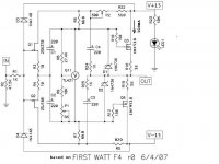
With your schematic as reference would it be possible to connect transformer between junction of R4/R3 and junction of C1/C2.
I would use Jack Ellianos PVA2-N as generg favored it in post 23 of MAGMA thread - http://www.diyaudio.com/forums/pass-labs/188109-introducing-magma-front-end-ba-2-f4-3.html
I believe it could also be wired as an autoformer. Cost is nice as 4 of these would be less than the Lundahls
Thanks
Bob
"- it's worth trying xformer as in M1 - nested between input buffer and output stage
- it's worth trying xformer connected as autoformer ; if you need drawing of that ,just say ."
With your schematic as reference would it be possible to connect transformer between junction of R4/R3 and junction of C1/C2.
I would use Jack Ellianos PVA2-N as generg favored it in post 23 of MAGMA thread - http://www.diyaudio.com/forums/pass-labs/188109-introducing-magma-front-end-ba-2-f4-3.html
I believe it could also be wired as an autoformer. Cost is nice as 4 of these would be less than the Lundahls
Thanks
Bob
Attachments
The Sowter mic input transformers for sale in swap meet would be a good inexpensive try at the concept. Sowter is a quality brand $30 can tb ebeat anywhere. If you like it, then you get to have fun trying different ones to find the perfect one. Ill be trying the sowter as soon as i get them.
Choky as you said
"- it's worth trying xformer as in M1 - nested between input buffer and output stage
- it's worth trying xformer connected as autoformer ; if you need drawing of that ,just say ."
With your schematic as reference would it be possible to connect transformer between junction of R4/R3 and junction of C1/C2.
I would use Jack Ellianos PVA2-N as generg favored it in post 23 of MAGMA thread - http://www.diyaudio.com/forums/pass-labs/188109-introducing-magma-front-end-ba-2-f4-3.html
I believe it could also be wired as an autoformer. Cost is nice as 4 of these would be less than the Lundahls
Cost of the Sowters buzzforb recommends if appropriate are even better. Haven't heard back from seller.
Thanks
Bob
Choky as you said
"- it's worth trying xformer as in M1 - nested between input buffer and output stage
- it's worth trying xformer connected as autoformer ; if you need drawing of that ,just say ."
With your schematic as reference would it be possible to connect transformer between junction of R4/R3 and junction of C1/C2.
I would use Jack Ellianos PVA2-N as generg favored it in post 23 of MAGMA thread - http://www.diyaudio.com/forums/pass-labs/188109-introducing-magma-front-end-ba-2-f4-3.html
I believe it could also be wired as an autoformer. Cost is nice as 4 of these would be less than the Lundahls
Thanks
Bob
for your balanced F4 can iteration , you need xformer with center tapped secondary , or in other words - with two section secondary
either that , or using one xformer per leg ...... which isn't smartest thing if you can choose
I don't know does PVA2-N have CT secondary
either that , or using one xformer per leg ...... which isn't smartest thing if you can choose
Choky
Is this not wise because of the variation of one transformer to the other?
Thanks
Bob
Choky
Is this not wise because of the variation of one transformer to the other?
Thanks
Bob
I'm living in believe that two phase balancing act is much more intimate , if happening in one magnetic circuit
one thing is , say , if you have normal M2 and you want to bridge it
another thing is if you're going to make balanced M2 from scratch
one thing is , say , if you have normal M2 and you want to bridge it
another thing is if you're going to make balanced M2 from scratch
buzzforb - thanks for info
Choky - I understand your belief that best sound comes from one magnetic circuit
Nelson - thanks for recommendation - a couple of questions if you don't mind - remember it takes time for this to sink in my brain
Are you recommending one of the Jensens in each of my R-, R+, L+, L- legs?
Can they be connected at junction of R3/R4 (input) and junction of C1/C2 (output) on the F4 board?
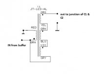
I think wiring as a autoformer is grounding brown lead, connecting red and orange and using that as input, connecting yellow/ green, connecting blue/violet and using grey as output (ref http://www.jensen-transformers.com/datashts/123alcf3.pdf)
Thanks again to all and for anyone looking for a headphone amp - a balanced F4 is at the top of my list
Choky - I understand your belief that best sound comes from one magnetic circuit
Nelson - thanks for recommendation - a couple of questions if you don't mind - remember it takes time for this to sink in my brain
Are you recommending one of the Jensens in each of my R-, R+, L+, L- legs?
Can they be connected at junction of R3/R4 (input) and junction of C1/C2 (output) on the F4 board?
I think wiring as a autoformer is grounding brown lead, connecting red and orange and using that as input, connecting yellow/ green, connecting blue/violet and using grey as output (ref http://www.jensen-transformers.com/datashts/123alcf3.pdf)
Thanks again to all and for anyone looking for a headphone amp - a balanced F4 is at the top of my list
two things , unfortunately :
1. I'm not Pa
2. yes , with Jensen , being xformer sans CT secondary , you must use one per leg
3. looking at schm you posted in #3390 , connection is like attached :
4. #3 and #4 are just to confuse you , considering two things mentioned
1. I'm not Pa
2. yes , with Jensen , being xformer sans CT secondary , you must use one per leg
3. looking at schm you posted in #3390 , connection is like attached :
4. #3 and #4 are just to confuse you , considering two things mentioned
Attachments
Last edited:
By that drawing, autoformer would be
BRN to GRY
VIO to BLU
GRN to YEL
RED = GROUND
ORG = OUT
BRN = IN
Correct me if I'm mistaken, ZM
😎
BRN to GRY
VIO to BLU
GRN to YEL
RED = GROUND
ORG = OUT
BRN = IN
Correct me if I'm mistaken, ZM
😎
- Home
- Amplifiers
- Pass Labs
- F4 power amplifier