Tim, where did you get those binding post?
I think they are these...
Dayton Audio BPP-G Premium Binding Post Pair Gold

Oh,input is wired to wrong NPN, actually it is at other NPN's base
EDIT: Added picture.. Estimated values of components. Also, I think I could wire NTC in series with bias regulating pot ( 14k resistor in diagram),so bias current doesnt drift.
EDIT: Added picture.. Estimated values of components. Also, I think I could wire NTC in series with bias regulating pot ( 14k resistor in diagram),so bias current doesnt drift.
Attachments
Last edited:
Another pair of F4's
Hi,
I have been reading the forum for some time and decided to build a pair of F4's. That way I can use them stereo (single ended) or as mono blocks (balanced).
BTW Just wondered if you can do the same trick with the F5 (that is use them as a balanced mono block).
I have read many (way too many!) pages on this forum in order to figure out what I needed to buy. I think I have got it pretty well sorted (famous last words ...).
Anyway, due to a muscle disease I am wheelchair bound and pretty much useless at manual work. A friend of mine used to work for Hollandse Signaal, soldering quite a lot of top-secret military electronics (radar, etc). He is now retired (and bored) and was looking for a nice project to keep him occupied. Well, no prize for guessing who is putting my F4's together for me!
I have decided to go the easy route. I am using the v2.0 DIYAudio boards, parts from TechDIY, Digikey, Mouser, Amplimo, Hifi2000 (3U 300mm full aluminium, black).
I will try to upload a few photo's of the pcb's and the heatsinks later.
A few small questions:
I have no power supply pcb's and was planning to use polycarbonate or some other material with parts on one side and a few lengths of thick solid copper wire on the other. Any suggestions?
PSU capacitance.
The F4 and F5 manuals specify 15000uF 25V capacitors for C1-C8. I think I read somewhere that this should be 1500uF. I think I also read that Nelson wrote that the Elna Silmic II is much better and that you should double the number if you use the 1000uF. I now have [For each F4 (= for 1 SE stereo or 1 balanced mono block)]:
- 16 x 1000uF 35V Elna Silmic II (2 for each C1-8)
- 8 x .47 3W Panasonic (as original specs)
As we have not yet started on the power supply I can change anything I like. Do I have enough capacitance? Any other suggestions?
Thanks,
Albert
Nope. 15000uF per cap not 1500uF. Paralleling smaller caps to equal the 60,000 uF per rail (120,000 total) would be nice...but EXPENSIVE. Apex JR has 18000uF/25V panasonic for 2.50 per piece. He also has other helpful things. He has a thread in the vendor section.

Nope. 15000uF per cap not 1500uF. Paralleling smaller caps to equal the 60,000 uF per rail (120,000 total) would be nice...but EXPENSIVE. Apex JR has 18000uF/25V panasonic for 2.50 per piece. He also has other helpful things. He has a thread in the vendor section.
Oops
I checked my notes to see where I got the information from. Post 3085.
http://www.diyaudio.com/forums/pass-labs/97540-f4-power-amplifier-309.html
I also see that someone pointed out the error in a later posting.
So, now what? I have 32 x 1000uF Silmic II caps for 2 F4's. I can buy higher capacitance Nichion of Panasonic (or something else) to replace them, or could put some cheaper high-capacitance caps in the first part (CRC) and put the Silmic's, with some extra stuff, in the last (CRC)? I assume the latter to be more important but am not sure if this is correct.
If I "mix and match", what sizes and which configuration? Or am I in "any ones guess" territory?
Thanks,
Albert
Since you got them, you could do Big C -> Big C -> Resistors -> Big C - > Silmics. May be overkill and not worth the effort, but i don't know for sure. Build looks fantastic so far. You do know that this is a unity gain amp and you will need a pre that can swing 20V.
Build looks fantastic so far.
Thanks. I will pass it along to Jaap who is building them.
You do know that this is a unity gain amp and you will need a pre that can swing 20V.
Yes, I am aware of this. Jaap started on a Alpeh P1.7 for me 4-5 years ago. We bought all the parts from a Dutch supplier (he supplied KK PCB boards). This was before I started reading this forum and realised Nelson frowns on suppliers that offer kits.
Anyway, we had very little information and had no idea what we were doing (we bought a kit, right?!). We assumed the kit was a complete clone and had not realised that the volume control and input selection were cheap chinese parts. To cut a long story short, the supplier is no longer around so no-one was available to help us out when we ran into problems. Jaap cannot read English and I had no electronics knowlegde, so we just left it on the shelf to finish another day.
I started reading up on the subject last year and found out that we had inferior volume control and input selection boards. After reading manuals etc. we got the rpeamp itself running but it still nees a decent aluminium box, volume control and input selection. I am contemplating the dantimax boards but have not yet decided. Can't buy the box till we know board sizes. Input is appreciated!
My setup consists of stuff I bought cheaply second hand.
I use a Jeff Rowland Consummate preamp (ca. 20 odd years old). I am not sure how much voltage it swings but if I remember correctly I can set the gain to 19dB.
The Consummate single ended outputs feed into an original Pass Labs Aleph 3. It powers the mid/high of my Magnepan MGIIIa's.
The Balanced outputs of the Consummate go to a cheap Behringer electronic crossover. Its high outputs are disconnected (I tried running the Aleph 3 off them but it ruined the sound; running the mid/high panels without a low filter seems to work fine). The low output feed into an old class AB poweramp that powers the bass panels.
I love the sound of the Aleph 3 and ran the MGIIIa's with just the Alpeh 3 for a while, but it is just too small. This is why I bought the Behringer and the second hand class AB.
I am hoping that the balanced F4 monoblocks will be a better match for the mid/high panels of my MGIIIa's.
If the Aleph 3 can handle the top, and your original crossovers are still good, the F4 can feed off the Aleph 3 and run the low end. Is this what you were thinking? If your original crossovers are still good, the Behringer should be unnecessary.
No, I will be looking for some high efficiency speakers for the Aleph 3 (with the Aleph P1.7 when it is done). I can then use it in my study.
I plan to use the F4's (balanced) instead of the Aleph 3.
The old class AB handles the bass well, so no point in changing it.
Not sure about using the old external crossovers. I guess I can ditch the Behringer (the old class AB has plenty of power so I can drop some in the external crossovers) but I will have to put in some kind of attenuation to ensure that levels are matched.
I was hoping for a DIY version of the B4 or B5, but I do not think they will be available for DIY soon.
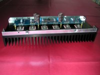
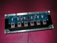
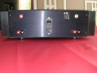
F4 photo's
Quick update on our build. We are using the 3u 300mm all aluminium cases from Hifi2000 in Italy. Jaap has finished drilling, cutting and filing holes in the back covers and has installed the cinch and XLR inputs, the speaker binding posts and the power entry modules. He has done a beautiful job!
BTW I decided to use a power entry modules rather than a separate entry units, switches, mains filters and fuse holders. This unit switches both hot and neutral wires and has an inbuilt (dual) fuse box and mains filter. It is rated 6A, so should be more than adequate.
N.B. The case is straight. It is the lens that makes it look rather curvy
Attachments
Oh, surprise! 😀
When I looked at the F4 scheme at the diyaudio store, after a remark of buzzforb, I saw also the changed values
- source resistors of the j-FETs from 10 to 22 Ohm
- 2x220uF on all places we had 220uF only
- two 0,47 Ohm parallel instead of one 0.47 Ohm source resistor for all mosfets
What are these changes doing? I suppose less output impedance, less stress for the j-FETs and less turning on plop?
Anybody knows better? 😕
The larger source resistors would mean more linearity through degeneration, correct? I was just thinking whether or not Nelson had a reason for such changes. He goes even further with the BA outputs and makes the source resistors 1R.
Hey cviller,
I hope you have fine weather, like me.......🙂
The link is in the store.....
http://www.diyaudio.com/forums/imag...cumentation/P-F4-1V20/P-F4-1V20-schematic.pdf
If anybody knows if it is official it is you.... 🙂
I hope you have fine weather, like me.......🙂
The link is in the store.....
http://www.diyaudio.com/forums/imag...cumentation/P-F4-1V20/P-F4-1V20-schematic.pdf
If anybody knows if it is official it is you.... 🙂
Last edited:
Buzzforb, 🙂
Nelson takes the 1 Ohm also to reduce the current through the stages, especially when you take 6 pairs, but he also says that with three pairs you should take possibly 0,47 Ohm.
I think higher source resistors also do not so well matched IRF
😀
Nelson takes the 1 Ohm also to reduce the current through the stages, especially when you take 6 pairs, but he also says that with three pairs you should take possibly 0,47 Ohm.
I think higher source resistors also do not so well matched IRF
😀
Yes, it is nice and sunny - almost too bright for the laptop! 😀
It is official against the boards offered - but if you notice, the extra components you are observing, these are numbered 1XX instead of XX. They are actually only there to support extra footprints. You can find the most recent schematics that I am aware of here:
http://www.diyaudio.com/forums/blogs/cviller/198-my-f4-guide.html
It is called f4r0.pdf
So basically, there are no doubling of components - only the source resistors seem to have changed between some of the iterations, but in the production service manual, papa has kept the 10ohm source resistors on the jfets.
They are actually only there to support extra footprints
That means I could take 2x 100uF or 2x 1 Ohm?
But for normal people it is difficult to see it with your eyes....
And the shop has no contact possibility, so it should not make an own scheme I think...
Best for you
Gerd
- Home
- Amplifiers
- Pass Labs
- F4 power amplifier