Save three pairs for me, just in case. PLEEEEEEEEEEEEEEEEEEASE. I have two sets of board and will happily do a amp to amp comparison.
Yes i will do it!
🙂
Yes i will do it!
🙂
I made a stupid mistake and said three. I realize that I would need 6 pairs for an F4. FWIW, If it doesn't work out, I have a source that has them available for about $4/pair unmatched. I really appreciate it either way Generg.
Hi buzzforb,
Maybe 6 Pairs will not work, if the 25+25 are not matched closely....
But we will see.....
Maybe 6 Pairs will not work, if the 25+25 are not matched closely....
But we will see.....
Woudl it make a huge difference to change the gate resistors to 150r. I don't have enough 100r. I know it would mostly affect the the level at which the TL431 is adjusted. I have seen as much as 220 on the gates of the IRF fets, so would think it would be OK, but i can't say that i understand how the values of gate resistors are arrived at.
Woudl it make a huge difference to change the gate resistors to 150r. I don't have enough 100r. I know it would mostly affect the the level at which the TL431 is adjusted. I have seen as much as 220 on the gates of the IRF fets, so would think it would be OK, but i can't say that i understand how the values of gate resistors are arrived at.
As far as I got to know, it affects the bandwidth, and the tendency of the circuit to oscillate.
As far as I remember the gate resistor of F4 changed at least one time from 100 to 150.
I suppose the best would be to look with an oscilloscope which value is sufficient to get no oscillation.
150 is more on the secure side.....
Nevertheless I could hear the difference in sound between 100 and 220.
But it is possible that I heard the mix of music and hidden oscillation at the lower value and the pure sound with the higher value.......I believe......
Thanks Generg. THat s what i thought, but i did not know about the correlation to sound. I am putting together first F4. I will probably due the crippled BA version first and add other FE components later with switch allowing their use.
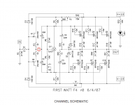
Generg, How do you have your F4 setup to use both ways? I am trying to figure out whether to follow the Ba setup or F4. THe F4 has components like R24 and R25 that are there for the Jfet FE but not used in BA amp. Having them connected shouldn't hurt as they are just part of a bootstrap setup. Also. the BA amp is connected to ground between two smaller Caps, while F4 is connected to ground at the Input. Last question. THe voltage diverder network setting the regulator is smaller on the BA output than the F4. I would assume this just affects the impedance.
I made a break at the red place and open and close it and give the signal either to the j-fets or, the red place open, directly to the MosFets.
In one of the posts of the thread somebody measured the input impedance with the bootstrap setup and he said there are about 60k for the Mosfets only, so it is no problem to fed the signal directly in the MosFets.....
In one of the posts of the thread somebody measured the input impedance with the bootstrap setup and he said there are about 60k for the Mosfets only, so it is no problem to fed the signal directly in the MosFets.....
Attachments
Look what Nelson wrote in post 2913
"Originally Posted by Nelson Pass
If you have a source which can drive 5 Kohm and a couple hundred pF,
you can dispense with the JFETs altogether and simply drive the Gates
of the Mosfets.
A little more work, and you can use a single pair of Mosfets and raise
the impedances of the bias circuit, and then it would be about 22K and 70 pF."
or scorpio post 2985
"have tried and found the following up till now:
Standard: input impedance= 5k, gain approx. 0.93gg
Bootstrapped: input impedance= 64k, gain approx. 0.93gg
I have added a switch to be able to select between the two, but with my tube prestage bootstrapping is best. "
🙂
I made a break at the red place and open and close it and give the signal either to the j-fets or, the red place open, directly to the MosFets.
In one of the posts of the thread somebody measured the input impedance with the bootstrap setup and he said there are about 60k for the Mosfets only, so it is no problem to fed the signal directly in the MosFets.....
That is what i had intended to try. What about grounding C3/C4 like in the BA-3 output.
Also. the BA amp is connected to ground between two smaller Caps, while F4 is connected to ground at the Input. Last question.
Hi buzzforb, I do not see what you mean.....?
That is what i had intended to try. What about grounding C3/C4 like in the BA-3 output.
When you ground them they have no longer the bootstrapping function I suppose.....!
My concern is whether or not it needs to be grounded if using the amp as BA style output. In the F4, it is a bootstrap setup, so it is tied to the output. In BA output, those caps are grounded and not tied to the output. I guess it shouldn't affect performance since you have had it that way.
O.k. Now I understood....
I do not know if you need the connection point really, I remember that Nelson wrote that the F4 with bootstrap solution had a little better distortion values....
In BA-2/1 you had a bootstrap from the output to the old front end ..... Hm, hm
Gerd
I do not know if you need the connection point really, I remember that Nelson wrote that the F4 with bootstrap solution had a little better distortion values....
In BA-2/1 you had a bootstrap from the output to the old front end ..... Hm, hm
Gerd
Link for explanation od bootstrapping of F4.
http://www.diyaudio.com/forums/pass-labs/155835-f4-schematic-feedback-circuit.html
First time i have seen it used this way. Normally used to reinforce current source like in BA-1/2. Here it seems to steady rail voltages, which i guess works by stabilizing jfet Vds. Don't know if thats correct or not.
F4 PSU
Hi,
I have previously asked some questions about the F4 PSU (and PSU's in general) and have been given excellent advice!
I think I have now worked out how to do it, but would like some reassurance. I did not want to clutter up this thread so put it on another. It is in two parts: Messages 20 and 21.
http://www.diyaudio.com/forums/pass-labs/196512-generic-poweramp-power-supply-questions-2.html
I would appreciate it if someone with a bit more experience can give me the OK.
Thanks,
Albert
PS Was not sure if I should post this or not. Since it is F4 related I thought it would be OK.
Looking back at my first post in May, I realize it has taken me nearly 6 months to finish my two F4 Hybrid mono-block amplifiers. Anyway they are working now so here are some images. These may be unique as they have a tube based front end and are configured as dual mono for each channel rather than the usual balanced mode. I did this as they are to designed to drive two Martin Logan Ethos electrostatic speakers. These have a nominal 4 ohm impedance, but this rapidly drops to 2 ohms and below at higher frequencies. So I chose current drive over voltage.
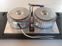
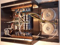
I built and tested the amps as a series of sub modules. The first image shows the power supply unit, with one PC and caps for each amp in the chassis. I went overboard with the PSU, using 2 x 18V 500VA transformers in each channel.
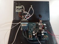
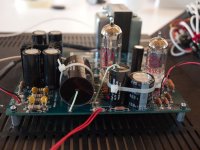
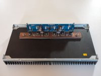
The next two images are of the tube based front end. This is the "Unbalancer" from GlassWare Audio. The first tube is a differential input with 14dB gain, while the second is a Broskie cathode follower to give a single ended drive to the two amplifier modules.
As the heatsinks in the chassis come in two parts, I mounted the power fets on copper bars bolted to the heatsinks to provide more uniform thermal matching. All the modules were set for an average of 200mV over each of the 0.47 ohm drain resistors. Final wiring was a mixture of hookup wire and some old QED silver Loudspeaker wire stripped into two strands. Apart from the PSU overkill and the Caddock solid copper loudspeaker posts, the other exotic items are the signal path capacitors in the valve front end.
With a 1kHz tone, I measured 100Watts over a 2.3 ohm load resistor. I have not pushed it much higher as I do not have a distortion meater to measure peak power in any case.
The final image shows one amp powering an Ethos. I will report later on the sound as some of the components - especially the exotic caps - seem to need 200 - 400 hours of running in before serious listening!
PJG
I built and tested the amps as a series of sub modules. The first image shows the power supply unit, with one PC and caps for each amp in the chassis. I went overboard with the PSU, using 2 x 18V 500VA transformers in each channel.
The next two images are of the tube based front end. This is the "Unbalancer" from GlassWare Audio. The first tube is a differential input with 14dB gain, while the second is a Broskie cathode follower to give a single ended drive to the two amplifier modules.
As the heatsinks in the chassis come in two parts, I mounted the power fets on copper bars bolted to the heatsinks to provide more uniform thermal matching. All the modules were set for an average of 200mV over each of the 0.47 ohm drain resistors. Final wiring was a mixture of hookup wire and some old QED silver Loudspeaker wire stripped into two strands. Apart from the PSU overkill and the Caddock solid copper loudspeaker posts, the other exotic items are the signal path capacitors in the valve front end.
With a 1kHz tone, I measured 100Watts over a 2.3 ohm load resistor. I have not pushed it much higher as I do not have a distortion meater to measure peak power in any case.
The final image shows one amp powering an Ethos. I will report later on the sound as some of the components - especially the exotic caps - seem to need 200 - 400 hours of running in before serious listening!
PJG
Attachments


- Home
- Amplifiers
- Pass Labs
- F4 power amplifier