Hi Zen Mod,🙂
you suggested:
"omit output caps on , omit everything in front of two electrolyt caps on F4 input ( tossing out jfet buffer and everything related) , bypassing two elcos with 10-68nF polycarbonats ........ then tell me what's your impression"
I am going in balanced, but going out unbalanced to F4. Should I also omit the caps of the output shortened and then shorten the unused output?😕
I hesitate a little bit because the voltage on the outputs of pumpkin is coming down very slowly to zero volt. I lasts about ten to fifteen minutes. Is this behaviour o.k.?
Should I keep the output cap of the unused and shortened output?
I dont´t want to destroy pumpkin!!!!!!!!😱
Sounds like that is a yes. Either that or you need to warm up the pumpkin before turning on the F4. Otherwise you will nuke your speakers. The DC offset on the pre will just be amplified by the F4 and potentially do damage to the speakers.
Hi Zen Mod,🙂
you suggested:
.........
I'll prepare little sketch later
no need to worry .....

Hi Zen Mod,🙂
you suggested:
"omit output caps on , omit everything in front of two electrolyt caps on F4 input ( tossing out jfet buffer and everything related) , bypassing two elcos with 10-68nF polycarbonats ........ then tell me what's your impression"
I am going in balanced, but going out unbalanced to F4. Should I also omit the caps of the output shortened and then shorten the unused output?😕
I hesitate a little bit because the voltage on the outputs of pumpkin is coming down very slowly to zero volt. I lasts about ten to fifteen minutes. Is this behaviour o.k.?
Should I keep the output cap of the unused and shortened output?
I dont´t want to destroy pumpkin!!!!!!!!😱
naah ..... no need for sketch
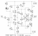
use F4 schematic from post #2994
connect
 as usual ( pos out to F4 , neg to gnd ) then bridge output cap on positive out with piece of wire .
nothing wrong will happen - ya see that 10K from output to gnd in Pumpie itself ?
Hi Zen Mod,
I modified, genergMod is happy!
What a sound, so natural. The the "k3 sound of F5" is very impressive, but you always want more and more details. F4 doesn´t reveal so much, but keeps more coherence and the details come as a surprise!
This keeps me calm and emotionally more satisfied.......
Pumpkin and of cause the wonderful DIY-amplifiers of Mr. Pass deserves the best attenuators in front of them you can get. I tried many possibilities, tvc (slagle) and a stepped attenuator (glasshouse) were the best in my chain.
Thank you again for helping so fast and competent!
😉
ZM is here , as always , to serve and protect

Ha,ha Robin Zen Mod!


Help with F4- no sound
Hi all,
Several months ago, I built a pair of F4 monoblocks using Peter Dianiel's boards. Worked good until yesterday, when I lost sound from left channel (right channel continued to work well). Substitution of different amp (nothing else changed) restored sound.
Voltage across all six 0.47R resistors (R16-R21) is 200mV at start-up. DC offset at binding posts is 30mV at start-up. Input RCA has correct continuity with signal and ground on PB. I cannot see any loose wires or smell burning. I do not know what else to check.
Any help tracking down the problem would be greatly appreciated.
Thanks
Gary
Zen Mod,
Thanks for your reply.
Voltage across R3 is 71.1mV. Voltage across R4 is 70.5mV.
Gary
Thanks for your reply.
Voltage across R3 is 71.1mV. Voltage across R4 is 70.5mV.
Gary
in that case everything seems fine - output mosfets are biased fine , current through input Jfets is in ballpark ;
desolder both input jfets , then inject signal at junction of C1 and C2 ;
if you get sound , replace both input jfets ;
if not - we'll see .....
desolder both input jfets , then inject signal at junction of C1 and C2 ;
if you get sound , replace both input jfets ;
if not - we'll see .....
Thanks to Zen Mod
Zen Mod- Your suggestion worked. I replaced both JFETs and adjusted DC offset. Sound is back.
Thanks for your help. Now I am ready to try Pumpkin.
Gary
Zen Mod- Your suggestion worked. I replaced both JFETs and adjusted DC offset. Sound is back.
Thanks for your help. Now I am ready to try Pumpkin.
Gary
F4 as a headphone amplifier
Hello
I have started building my second pair of F4 on Villers PCB. This time I intend to try out how it will work as a headphone amplifier for my AKG K701.
I do need some adwises form someone with a better electronic understanding than myself about (still running in classe A):
Power voltage (lower than +/- 23 V if possible) and bias per device.
Preamp will be B1
Specifications AKG K 701
Type: Circumaural, open back headphones
Efficiency: 105 dB SPL /V
Maximum input power: 200 mW
Impedance: 62 Ohms
I have a lot of 220uF/16 V cond. Can I use them as C1/C2.
What about C3/C4?
Sincerely
Eivind Stillingen
You can run the amp at lower bias when your load is 62 ohm - but sounds like you already know that.
You can use the 16V caps on C1 and C2, but it might be a good idea to lower the voltage too. C3 and C4 will see a higher voltage, so you need to be careful with those. If you don't plan on using any gain, then you can lower the voltage quite a bit and still have plenty of swing without clipping.
You can use the 16V caps on C1 and C2, but it might be a good idea to lower the voltage too. C3 and C4 will see a higher voltage, so you need to be careful with those. If you don't plan on using any gain, then you can lower the voltage quite a bit and still have plenty of swing without clipping.
MPP from Joachim Gerhard
Hi Eivind,
Go to the thread of Joachim and go to the 4 last pages. You'll find all you need to make a good Phone amp for your AKG.
Just my 2 cents,
Audiofanatic 😉
Hello
I have started building my second pair of F4 on Villers PCB. This time I intend to try out how it will work as a headphone amplifier for my AKG K701.
I do need some adwises form someone with a better electronic understanding than myself about (still running in classe A):
Power voltage (lower than +/- 23 V if possible) and bias per device.
Preamp will be B1
Specifications AKG K 701
Type: Circumaural, open back headphones
Efficiency: 105 dB SPL /V
Maximum input power: 200 mW
Impedance: 62 Ohms
I have a lot of 220uF/16 V cond. Can I use them as C1/C2.
What about C3/C4?
Sincerely
Eivind Stillingen
Hi Eivind,
Go to the thread of Joachim and go to the 4 last pages. You'll find all you need to make a good Phone amp for your AKG.
Just my 2 cents,
Audiofanatic 😉
F4 as a headphone amplifier.
Audiofanatic
"Joachims thread". Can you please be more precise where to find this thread?
Thank you!
So to my question about a suitable power voltage and a corresponding bias for F4 driving my AKG K701 62 ohm imp.
How much can I reduce both and still be in classe A. The reason I ask has influence on how big heatsinks I must use (I already have two that I hope will fit)
Sincerely
Eivind Stillingen
post 1088
on this side i suppose ....
http://www.diyaudio.com/forums/analogue-source/154210-mpp-109.html
good luck!
on this side i suppose ....
http://www.diyaudio.com/forums/analogue-source/154210-mpp-109.html
good luck!
F4 as headphone amplifier
generg
You wrote:
".... do you know this version of F4?
Could be enough for your headphone".
Do you mean that this can do the job alone, without B1 as "pre"?
How do I fix a volumecontrol?
The PCB I use is from cviller. Here is the schema he use:
http://www.diyaudio.com/forums/blogs/cviller/198-my-f4-guide.html
As you can see, it is a little bit different from the version you show me. If I go for that version, as far as I can see, I have to keep Q3 and Q6 on cvillers PCB board and skip out the rest of IRF240/IRFP 9240? Will it be nessecary take away all 0,47/100 ohm resistors or can they stay (that will be the easiest way)??
D3/D4 out?
What about P2: 500 ohm versus 5 Kohm
R5: 1Kohm versus 3,32 Kohm
R22: 750 ohm versus 1 Kohm
Sincerely
Eivind Stillingen
- Home
- Amplifiers
- Pass Labs
- F4 power amplifier