korben69 said:Hi Giacomo
Very nice amp, I'm glad to see the result of your work.
Congratulations !
I'm happy you like it, seems like your FETs and boards have found a warm home (actually a hot home, I'm still playing with BIAS).
Thanks again for the nice stuff, without you I'd have gone crazy, wiring in air 😱
Giacomo
I have another question:
What would be the ideal impedance for the F4 used in bridged-mode ?
I am running here a DIY-Linesource with 12 ribbons and 18 4" drivers in series/parallel-setup of the drivers as two-way speaker with a simple 6db-X-over...so, I can influence the impedance queit significantly by simply connecting the drivers differently...if the F4 cares and if this really contributes.
Currently the impedance of my speaker is:
- 20Hz: 8 Ohms
- 40 to 120 Hz: above 10 Ohm with 80Hz: 18.3 (first impedance max)
- 200-600 Ohm around 6 Ohm with 280 Hz: 5.4 Ohm (all time low)
- 1300Hz-4000Hz_ above 10 Ohms with 2000Hz: 13 Ohm (second impedance high, x-over frequency)
- 8000 Hz and above: 8.4 Ohm
sooo....I could bring the wholespeaker down to 6 Ohm by paralleling more tweeters and put more RLCs into the X-over...do you think this matters for a F4 ? It will require re-work of the X-over, so if it does not matter if the F4 works into a 12 ohm or into a 6 ohm speaker...I will not touch it.
Quick question, mates: what's the actual BIAS current intended by Mr. Pass? I find both the .53 and .43 A spec around here.
I'm asking because my actual vdrop on the source resistors is 230 mV average, meaning about .49 A... And I think it's too hot, I can only touch the heatsinks for a few seconds (in the hottest area), then it definitely hurts.
Lowering the BIAS down to about .45A lets me hold my hand on the sinks forever, but I haven't tested if sonics will degrade or not, it's still burning in. What do you think? I don't know very much about correlation between BIAS and audio performance, I'm wondering if it's best to find a solution to run it near .5A, or simply get closer to .43-.45 and be fine.
Thank you very much.
Giacomo
0.6A per output device makes 3.6A peak output current in Class A.
Which makes straight-A 50W peak in 4 Ohm.
You don't have much choice besides going down, the lesson learned that you get never have big enough a heatsink if you're messing with Santa.
Which makes straight-A 50W peak in 4 Ohm.
You don't have much choice besides going down, the lesson learned that you get never have big enough a heatsink if you're messing with Santa.
jacco vermeulen said:0.6A per output device makes 3.6A peak output current in Class A.
Which makes straight-A 50W peak in 4 Ohm.
You don't have much choice besides going down, the lesson learned that you get never have big enough a heatsink if you're messing with Santa.
Jacco, what I've got here is two 30x24x4 cm heatsinks, not little puppies... It's almost twice as much as Nelson's commercial F4, from what I can see in pictures. They're not black-anodized... Does it make SO much difference?
I'm impressed with this lack of efficiency.
Giacomo
OK It isn't fired up yet in this rebuilt version, but it HAS been fired at Burning Amp so I doubt there are major complications.
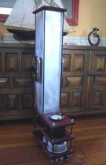
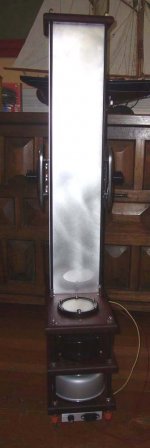
I was striving for the "mad scientist" look something that might have been in a lab many years ago..
The lowest level has the toroid ransformer in the silver can , and the small heatsink has the diode bridges ( IXSS)
On the second level the black cans are chokes, so it has a pi supply: Caps-chokes-caps. The actual amp circuitry is under the side covers of the the "stack" The stack is 6"x6"x 3/16" aluminum tubing. In some photos you can see 3 of the 6 MOSFET's per channel
Total height is 44" (115cm) tall . A lot of amps end up on the floor, why not make 'em tall with a smaller footprint?
Anyway, just a bit more to go- (such as move the power cord to the rear) and neaten up the wiring so it will last...
Mark
Attachments

Variac, now you need to build a couple of BIB speakers, something tells me that they will aesthetically pair well with your amps! 😎

Thanks guys! I will post a couple more photos taken outside so there is more light, and some close-ups, when they are finished.
Vix, I am a big fan of BIB's and have built a couple. In a month I am having a Speaker Day where I have convinced some friends and family to show up and we will all work to make them each a pair of BIB's based on the Pioneer BOFU, BUFU, B20 whatever- you know the 8" with the whizzer cone.. I think that we will build about 8 pairs. They sound so good for so little money that I am kinda forcing these people to get some!!
But your point has occured to me.... I could make a pair of BIB's that match the amps in a lot of ways and they would look mighty cute together.(if "cute" and "big" can be the same) In fact it occured to me that a somewhat bigger aluminum tower could be a bib speaker AND a heatsink!! It wouldn't have flow through ventilation , but if it is big enough that wouldn't matter. The only problem is that I have been somewhat convinced vibrations affect the sound..
mark
Variac,
Very,very Nice!
I am a little upset however... You beat me to it and I'll have to enjoy copy-cat status. Copy cat with a cool amp that is...😀
I've been sitting on some 4.5"aluminum sq. for some time.
sb
Very,very Nice!
I am a little upset however... You beat me to it and I'll have to enjoy copy-cat status. Copy cat with a cool amp that is...😀
I've been sitting on some 4.5"aluminum sq. for some time.
sb
sb
The tube idea works well. With the 4.5" tube maybe you could have two towers, side by side for a stereo amp and spaced apart a bit - one for each channel...
Would actually have more surface area than mine for the height..
The tube idea works well. With the 4.5" tube maybe you could have two towers, side by side for a stereo amp and spaced apart a bit - one for each channel...
Would actually have more surface area than mine for the height..
Nelson, do you have any additional advice on which impedance someone should calcluate a passive active.cross-oer which works well with the F4 ?
From the manual:
"You can take advantage of the same arrangement if you have drivers and you
want to make your own custom passive crossovers:
An alternative arrangement results when you create your own passive crossover
networks using resistors as loads and feeding the results to F4 channels. The
networks behave more ideally driving resistors than the complex impedance of
loudspeakers, and the resistor values can be set over a wide range of
impedances.. The loudspeaker drivers themselves benefit from the direct
connection to the low output impedance of the amplifiers."
?
Variac said:But your point has occured to me.... I could make a pair of BIB's that match the amps in a lot of ways and they would look mighty cute together.(if "cute" and "big" can be the same)
mark
Yeah, they would be tall, but the footprint would be WAF tolerable.
Two BIBs in corners, and two monoblock amps next to them. Like four big chimneys, giving it an unconventional, "industrial" look. It would surely look interesting, and no one would object. 😎
Vix said:
....... It would surely look interesting, and no one would object. 😎
except "she" one .......

- Home
- Amplifiers
- Pass Labs
- F4 power amplifier