Blitz said:Nelson, do you have any additional advice on which impedance someone should calcluate a passive active.cross-oer which works well with the F4 ?
You can set the input impedance of an F4 pretty arbitrarily, so it
makes it easy to construct a single-pole filter, or if you want 2 poles
(the 12 db/oct kind) you can use the high input impedance coupled
with the low output impedance to make a Sallen-Key type filter with
fairly high Q. This is the kind of thing you can pick up in a book on
filters, like Lancaster's "Active Filter Cookbook" where the active
element is a buffer without voltage gain.
I will eventually be covering some of this in the Buffer Extravaganza
Pt 2 article whenever it gets out.
unconventional, "industrial" look.
yeah the babes love that 🙄
I THINK that my wife will "let me keep them" as she has seen how much work has gone into them ..
so, how much will each device dissipate given the bias listed in the service manual? At some point I calculated 14.47W. I'm estimating the die as 16mm x 20mm, does that seem reasonable? Also, I noticed that Rjc is different for the p-channel and n-channel devices. I'm doing a (elementary) study on which board orientation will be best. I'll post results in a day or two for critique.
papa please forgive me for i have sinned--i found the source of my hummmm in my F4!!!!!! i kept wondering why the dc offset acted so wierd and different between channels---- then i had an oh sh@# moment"do you think i really did that!" yes i did-when i laid out my parts for the boards i put both p channel jfets on the left channel and both n channel jfets on the right. i clipped the top of the wrong fet off of each channel and tacked on the correct part and viola!!! quiet as the proverbial church mouse and no trouble dialing in the bias and offset.and i fixed it myself!!!---bet it even sounds better!!thanks for your help-bubba
ps-ordered the plitron trannie and parts for the f5 this week
ps-ordered the plitron trannie and parts for the f5 this week
Variac said:Don't worry bubba, that's the secret break-in method. They'll sing like angels now..... 😉
My secret break-in method is to reverse connect the input and ground OR output and ground connections...then hook up to an analyzer and watch the circuit scream. It would be better if I put BNC panel jacks on everything.
jacco vermeulen said:0.6A per output device makes 3.6A peak output current in Class A.
Which makes straight-A 50W peak in 4 Ohm.
You don't have much choice besides going down, the lesson learned that you get never have big enough a heatsink if you're messing with Santa.
So, here I am again; because of this problem (I can set a maximum bias of about .4A, with the amp still getting a bit too hot for my hands), I decided to black-anodize the whole thing. I've got friends who do that for free to me.
Hopefully, with the thermal efficiency increased by the black finish, I'll be able to reach the correct bias point and live happy.
The question is: being the anodized finish self-insulating, do you still recommend me to put anything between the FETs and the sinks?
Thank you,
Giacomo
giacomo_pagani said:
....
The question is: being the anodized finish self-insulating, do you still recommend me to put anything between the FETs and the sinks?
Thank you,
Giacomo
yup.
mica & goo is still one of best solutions .
Zen Mod said:
yup.
mica & goo is still one of best solutions .
Uhm, I still have the teflon tape pieces which I used until now... Are they bad?
(I mean these: http://img254.imageshack.us/img254/8369/img1959rkm6.th.jpg )
Giacomo
giacomo_pagani said:
Uhm, I still have the teflon tape pieces which I used until now... Are they bad?
(I mean these: http://img254.imageshack.us/img254/8369/img1959rkm6.th.jpg )
Giacomo
OK - they're good too , even if I prefer mica ;
next time - try with smaller picture ; I didn't saw anything even on that one

giacomo_pagani said:Does it make SO much difference? this lack of efficiency.
Giacomo,
excuse me, i forgot your Q.
Yeah, it does make a lot of difference.
The relationship between heatsink height and C/W value is not a linear one, and beyond a heatsink specific height value there's little to be gained.
Your heatsinks look like a Fischer SK56 model, similar to the KL146 by Seifert.
Their efficiency is pretty good up to the 125/150mm mark, beyond that height the spacing of the fins is too narrow to get enough airflow and the heatsink chokes.
Plus, the C/W value is measured at a higher heatsink temperature than you use it at, means a 0.25C/W heatsink is more like 0.30C/W at 50C.
Check page 70 of the Seifert catalog for the temperature graph of the KL146 : here
jacco vermeulen said:
.....
Check page 70 of the Seifert catalog for the temperature graph of the KL146.........
picture of you , in a middle of amp kuhlung ?

Attachments
Nope, that's Manuel.
Little read error: the KL-146 is at page 72.
Recognise the 0.025 C/W monster on page 100 ?
Little read error: the KL-146 is at page 72.
Recognise the 0.025 C/W monster on page 100 ?
jacco vermeulen said:.......
Recognise the 0.025 C/W monster on page 100 ?
nope ....... I'm in small league ;
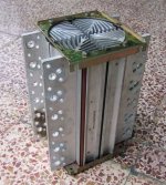
I have just this one :
Attachments
Nelson Pass said:
You can set the input impedance of an F4 pretty arbitrarily, so it
makes it easy to construct a single-pole filter, or if you want 2 poles
(the 12 db/oct kind) you can use the high input impedance coupled
with the low output impedance to make a Sallen-Key type filter with
fairly high Q. This is the kind of thing you can pick up in a book on
filters, like Lancaster's "Active Filter Cookbook" where the active
element is a buffer without voltage gain.
I will eventually be covering some of this in the Buffer Extravaganza
Pt 2 article whenever it gets out.
Here is a 3rd order Butterworth LP filter (458Hz) with a Sallen-key topology I'm working on (any comments are welcome...). I used a JFET type buffer (thanks Juma/Nelson) instead of opamps.
So Nelson, you're saying the last stage could be the F4? In my example, the last stage is the one pole, but it could be I guess the 2 poles one. Is there any advantage for that?
Thanks,
An externally hosted image should be here but it was not working when we last tested it.
In Building a Mosfet Citation 12 Nelson talks about using the amplifier to analize itself on page 12 of the pdf. Could this method be used to analize the F4 and play with adding an extra curent source to the output as described near the end of the new bias article?
- Home
- Amplifiers
- Pass Labs
- F4 power amplifier

