jleaman said:
I can re-try this again, ill set P1 to max, then P2 in the middle. Kinda hard to measure now that they are soldered to the board and the board is mounted.
Jase
Count the total turns of your pot and divide by two?
BTW, you'll chuckle if you reread the original posts........
Member
Joined 2002
carpenter said:
Count the total turns of your pot and divide by two?
BTW, you'll chuckle if you reread the original posts........
Yup i have done this still problems, one side of the fets warm up and the other doesn't. i ca hear it pulling current too, because my variac is humming 🙁 and the thermistor is getting HOT.
Member
Joined 2002
carpenter said:Can you get gate voltage to both banks of power fets?
I can try, however i'm not powering this amp up to full. Im scared to 🙁 i don't want to burn it out 🙁
Magura said:
Have you looked up the datasheets of the two diodes in question?
Magura 🙂

jleaman said:
I can try, however i'm not powering this amp up to full. Im scared to 🙁 i don't want to burn it out 🙁
Using your variac, turn on the amp a little (assuming P2 is centered) and measure voltage at power fet gates. I would imagine it should match.
Member
Joined 2002
carpenter said:
Using your variac, turn on the amp a little (assuming P2 is centered) and measure voltage at power fet gates. I would imagine it should match.
Measured from the psu and then measured from the gate, its the same on all.
I looked it up and the IRFP240 go like this, left to right GDS 🙂
Magura said:
Yeah, I know....Magura the moron...
Magura
nope , you moron!
ZM is moron!
Member
Joined 2002
jleaman said:any more thoughts for this ?
Hi,
What have you experimented with in the last 24 hours?
🙂
Member
Joined 2002
carpenter said:
Hi,
What have you experimented with in the last 24 hours?
🙂
Nothing 🙁 i worked all day hanging 60" plazma tv's 😛 i double checked the psu but thats about it so far.
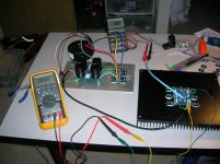
Should i add picture of some sort ?
Close-up pics are good to have. There are plenty of sharp eyes out there to help.
BTW, it never hurts to send a pic. You don't need to ask.
BTW, it never hurts to send a pic. You don't need to ask.
Member
Joined 2002

Member
Joined 2002
Member
Joined 2002
I think i have figure this out, GRRR,
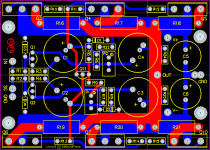
On peter's boards See attached picture, you will see C5 & C6, they tie grount together into the circuit, when i was asking LONG ago what i should put in here people were saying it just something extra however i can leave them out, so i did, looking at the board as i was just assembling the other board i saw that gnd at that end of the board was not even tied to the circuit 🙁 so i wonder if i should use the ground near the input then ? or should i put something into C5 & C6 ?
On peter's boards See attached picture, you will see C5 & C6, they tie grount together into the circuit, when i was asking LONG ago what i should put in here people were saying it just something extra however i can leave them out, so i did, looking at the board as i was just assembling the other board i saw that gnd at that end of the board was not even tied to the circuit 🙁 so i wonder if i should use the ground near the input then ? or should i put something into C5 & C6 ?
Attachments
Member
Joined 2002
lykkedk said:jleaman, what kind of isolation do you use on pwrmosfet's ?
Jesper.
Im using my trusty ceramic Isolation pads.
jleaman said:On peter's boards See attached picture, you will see C5 & C6, they tie grount together into the circuit, when i was asking LONG ago what i should put in here people were saying it just something extra however i can leave them out, so i did, looking at the board as i was just assembling the other board i saw that gnd at that end of the board was not even tied to the circuit 🙁 so i wonder if i should use the ground near the input then ? or should i put something into C5 & C6 ?
That ground connection is only when C5/C6 are installed, otherwise it's not being used. I explained it here: http://www.diyaudio.com/forums/showthread.php?postid=1324572#post1324572
- Home
- Amplifiers
- Pass Labs
- F4 power amplifier