It might also be worth to check out these pairs (not sure how official):
2n5462/2n5459
or
j271/j310
First with high voltage and second with better transconductance.
2n5462/2n5459
or
j271/j310
First with high voltage and second with better transconductance.
Now I've had some time to play with this little fine circuit in my simulater. First I had a hard time getting it to work and blamed it om my TL431 spice subcircuit. Later i found out that the 0.47 Ohm source resistors can't be 0.22 Ohm That is if you don't want to have 6 dB loss in the circuit.
I find the the way the 2 caps from the Jfet center bootstraps the output fets a stroke of genius. Thanks for shearing.
My question is regarding thermal tracking. Is this done by the TL431 or is it done by useing IRFP240 that dosen't seem to suffer as much from secondary breakdown.
I find the the way the 2 caps from the Jfet center bootstraps the output fets a stroke of genius. Thanks for shearing.
My question is regarding thermal tracking. Is this done by the TL431 or is it done by useing IRFP240 that dosen't seem to suffer as much from secondary breakdown.
That Class A amps can only get colder still is very elegant,imo.
Why bother to stick a TL431 on a heatsink.
(shear it off)
Why bother to stick a TL431 on a heatsink.
(shear it off)
MiiB said:Now I've had some time to play with this little fine circuit in my simulater. First I had a hard time getting it to work and blamed it om my TL431 spice subcircuit. Later i found out that the 0.47 Ohm source resistors can't be 0.22 Ohm That is if you don't want to have 6 dB loss in the circuit.
My question is regarding thermal tracking. Is this done by the TL431 or is it done by useing IRFP240 that dosen't seem to suffer as much from secondary breakdown.
I can't imagine why .22 ohms wouldn't work.
As to the temperature compensation, the circuit drifts positive
on bias, so of course you set it at temperature, and it's fine.
If you want compensation, just put a thermistor in series with
the resistance between the + and control pins. When I do this
I usually use another resistor in parallel with the thermistor so
I can box its range better.
😎
I ordered some 9240s and some jfets from Tech-Diy on Friday and they were in my mailbox today! Granted he's (?) in NJ and I'm right here in MA, but that's good service in my unhumble opinion. 🙂
-plug over
Now I will make an utter fool of myself (ahem, again). I have a question on this simple circuit that I should understand better, but don't
- Regarding the TL431, what exactly is it doing, and which way does it go in? I assume that the reference connects left (in schem), the anode connects neg, and the cathode connects pos. Am I right? Do I win the dunce prize?
Attachments
mpmarino said:- Regarding the TL431, what exactly is it doing, and which way does it go in? I assume that the reference connects left (in schem), the anode connects neg, and the cathode connects pos. Am I right? Do I win the dunce prize?
I think you are right about the pins of Ref, K and A.
The reference voltage between Ref-pin and A-pin is 2.5V
whatever resistor value (at proper current level) is between
those two nodes. Then, you pay a peanut for the calculation
of the voltage at K ^^.

Attachments
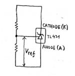
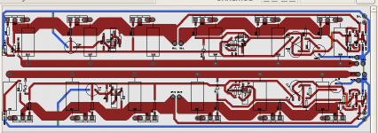
mpmarino said:which way does it go in?
Mark,
you can see the orientation of the TL431 on the board layouts.
In 1st grade HS chemistry class i learned OPA(grandpa) and HENK(origin of Hank) as memory clues for the electrolysis process.
Oxygen-Positive-Anode and Hydrogen-Negative-K(C)athode.
For electronic components i always think negative is where the current is drawn in, positive where it comes out. Retards Rule !
"What exactly is" doesn't count. You're disqualified too.

Thanks guys,
It makes sense to me now. For some reason the datasheet was clear as mud to me 🙄 and I had a hard time picturing it at work in the circuit.
It makes sense to me now. For some reason the datasheet was clear as mud to me 🙄 and I had a hard time picturing it at work in the circuit.
You've been waiting a couple days for that, haven't you"What exactly is" doesn't count. You're disqualified too.
After inspecting the layout is seems to me that P1 is wired "backwards"? That is, you increase bias by turning it counter-clockwise? This assuming a standard 5K (Bourns?) single turn trimmer is used. 😉
mpmarino said:For some reason
For some reason i don't get why there's not a uniform lead pattern for these devices, not even for same brand components.
National also manufactures the oldy LM335Z, besides the LM431.
Precision temperature sensor, but the +,- and Adjust leads are switched.
The LM335Z is a valuable friend for Class-A/Pretty-Pass amps, btw.
Months, if necessary !!
I ineterprete TL431 as a zener diode--but the diode giving us
flexible breakdown voltages inbetween 2.5V and max 36V
depending on the resistor values arranged between K, Ref and A pins.
flexible breakdown voltages inbetween 2.5V and max 36V
depending on the resistor values arranged between K, Ref and A pins.
Babowana said:I ineterprete TL431 as a zener diode--but the diode giving us
flexible breakdown voltages inbetween 2.5V and max 36V
depending on the resistor values arranged between K, Ref and A pins.
That's about right 😀 It's a "shunt regulator" . A refrence, an op amp and a pass transistor. It turns on and off the pass transistor to maintain the programed voltage. Probably about 8.5V or so???
One thing though. the terms Cathode and Anode? wouldn't they be + and - respectively???
flg said:
One thing though. the terms Cathode and Anode? wouldn't they be + and - respectively???
Cathode is (-) and Anode is (+).
why I have impression that Papa must be giggle now.............
edit:
any toob boy in panty hoses know that anode is on more positive pole,cathode is on more negative pole, and grid is more than often going south.................
I see that entire DIYa is predestined for massive harakiri............
edit:
any toob boy in panty hoses know that anode is on more positive pole,cathode is on more negative pole, and grid is more than often going south.................
I see that entire DIYa is predestined for massive harakiri............
To me papa doesn't seem like the giggling type...
ZenLite:
That's more like it! 😀
Can't wait for the laminate to arrive... 😉
ZenLite:
I built some with three 300 watt bulbs in parallel also:
BWAAAHAHAHAA!
That's more like it! 😀
Can't wait for the laminate to arrive... 😉
Attachments
cviller said:To me papa doesn't seem like the giggling type...
ZenLite:
That's more like it! 😀
Can't wait for the laminate to arrive... 😉
and WTF is this pic?
just joking ,off course
btw-where is there A and C ?
Zen Mod said:btw-where is there A and C ?
??? Still talking about anode/cathode?
cviller said:To me papa doesn't seem like the giggling type...
ZenLite:
That's more like it! 😀
Can't wait for the laminate to arrive... 😉
cviller - you are just as bad as Steenoe (building stuff so fast), but even worse - I just picked up 12"x12" copper clad board today to etch your babelfish layout and now you are teasing us with F4 layout ...
Of course, you will have to let us know how it sounds
😀
twitchie said:
cviller - you are just as bad as Steenoe (building stuff so fast), but even worse - I just picked up 12"x12" copper clad board today to etch your babelfish layout and now you are teasing us with F4 layout ...
Of course, you will have to let us know how it sounds
😀
Please let me know before you etch my fish... I have a few updates to for it.
Papa is the one teasing as all! I would love to see the aleph j too!

- Home
- Amplifiers
- Pass Labs
- F4 power amplifier