veteran said:Congratulations for Mr Pass and a present for you guys - another look on PCB for this amplifier 😉
care to share a bit more detail of this nice 1 sided layout, veteran?
cviller said:
Please let me know before you etch my fish... I have a few updates to for it.
Papa is the one teasing as all! I would love to see the aleph j too!
http://www.passlabs.com/np/AlephJSerM.pdf
Zen Mod said:
Looks like NP isn't the only tease 'round here

flg said:
One thing though. the terms Cathode and Anode? wouldn't they be + and - respectively???
That's what's on the datasheet... Cuase them SS people trying to use tuby terms
 And I guess cause it's a Zener picture???
I like my Anodes + and my Cathodes - ussually... enough of that...
zener diode
You might have guessed it from the diode arrow symbol orientation.
Some manufacturers avoid the confusion by using +/- notations instead of cathode and anode.
Welcome to Solid State.
You might have guessed it from the diode arrow symbol orientation.
Some manufacturers avoid the confusion by using +/- notations instead of cathode and anode.
Welcome to Solid State.
Mark,
them others didn't say "What is", all of them disqualified for the last couple of decades.
I suppose a Z-diode would scare the bl... out of Dracula too.
them others didn't say "What is", all of them disqualified for the last couple of decades.
I suppose a Z-diode would scare the bl... out of Dracula too.
jacco vermeulen said:ok, let's ask Choke what he has been eating today.
what else than this: (attached pic)
btw- A and C debate was just fun.......toob is toob,and zenner is just a zener ,no matter how complicated is ..........plain ole simple or zener-like chip........
Attachments

Different point of view on F4 amplifier PCB 😉 Ground connected in only one point.
schematic
PCB top view
PCB bottom view
schematic
PCB top view
PCB bottom view
Nice! 😉
Have you had time to etch and build the thing? Do you have some special heatsinks since you decided to have output fets on both sides?
I'm still waiting for the laminate to arrive - 1 layer pcb seems to be difficult to obtain in Denmark these days... 😕
Have you had time to etch and build the thing? Do you have some special heatsinks since you decided to have output fets on both sides?
I'm still waiting for the laminate to arrive - 1 layer pcb seems to be difficult to obtain in Denmark these days... 😕
Not yet, but I will probably order few to make sure, that there are no mistakes (schematic and layout is very easy so there shouldn't be any surprises). I have 200mm high heat-sinks and they will feat just fine 😉
If somebody want to have less problems with matching FETs - IRFP240/IRFP9140 should work better in output stage (I was using such pairs in Dracula amplifier). I added RA,RB and CA, CB components on this PCB but they can be skiped (just place jumper instead of RA and RB).
3D view of this board:
If somebody want to have less problems with matching FETs - IRFP240/IRFP9140 should work better in output stage (I was using such pairs in Dracula amplifier). I added RA,RB and CA, CB components on this PCB but they can be skiped (just place jumper instead of RA and RB).
3D view of this board:
Attachments
Thanks for sharing veteran,
I don't know if the day will come that I can do a nice layout. I have had a couple of successes but 🙄 Maybe someday I'll have something worth sharing
Jacco and Choky... be quiet!🙂 🙂 🙂 🙂 🙂 🙂 🙂 🙂 🙂 🙄
I don't know if the day will come that I can do a nice layout. I have had a couple of successes but 🙄 Maybe someday I'll have something worth sharing
Jacco and Choky... be quiet!🙂 🙂 🙂 🙂 🙂 🙂 🙂 🙂 🙂 🙄
mpmarino said:.........................
Jacco and Choky... be quiet!🙂 🙂 🙂 🙂 🙂 🙂 🙂 🙂 🙂 🙄
why ?
we always behave..........

Zen Mod said:
why ?
we always behave..........
Right.....🙂
Hey, would it be a big deal if the ZENERS were 6.2v as a sub for the 6.8v in the circuit?
Oh, are Jfets wicked static sensitive?
mpmarino said:
Right.....🙂
Hey, would it be a big deal if the ZENERS were 6.2v as a sub for the 6.8v in the circuit?
Oh, are Jfets wicked static sensitive?
you mean crippled 2N4736.......
they're there just for protection- just put what you have in drawer or don't put anything if you are confident that you wouldn't have short circ between headphones during connecting cables to amp
you mean crippled 2N4736.......
right...🙂
... and thanks.
The ZENERS look to be there to protect the OP FETs, right? Is it not necessary to protect the Jfets? Aren't those little buggers fragile?
fragile : (fra-geel-ae) 1. made in italy
mpmarino said:The ZENERS look to be there to protect the OP FETs, right? Is it not necessary to protect the Jfets? Aren't those little buggers fragile?
fragile : (fra-geel-ae) 1. made in italy
When we adjust bias voltage, e.g. TL431, we could make a
mistake by accident. If the bias voltage is too high,
the power mosfets would suffer from excessive current.
If so, when we have no spare parts, hmm . . .
Meanwhile, the input jfets are formed with self bias. As long as
the rail voltages are under control, the jfets are safe. In my
opinion, the probability for us to use wrong rail voltages are
ignorably low.

mpmarino said:
.................. Aren't those little buggers fragile?
fragile : (fra-geel-ae) 1. made in italy
not like m-fets
you don't need gate protection for them,except maybe few dozen ohms in line with gate................for radio freq
fragile?
krhki,you mean?
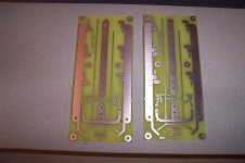
My first etching 
Thanks to Nelson Pass for sharing the schematic
Thanks to Veteran for sharing the layout
Thanks to Tom Gootee for the 'how to etch' instructions
Thanks to Nelson Pass for sharing the schematic
Thanks to Veteran for sharing the layout
Thanks to Tom Gootee for the 'how to etch' instructions
An externally hosted image should be here but it was not working when we last tested it.
- Home
- Amplifiers
- Pass Labs
- F4 power amplifier