
lykkedk said:
Hehe... ok cool Magura, but that's not something i have a picture off. !!! (I feel it's something different you try to tell me through)
Well, it's the connection's to the three different's setup's i am interested in 🙂
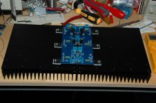
here's a picture of my initial setup... (I have changed R9 into 6,8kohm, else the bias wouldent go higher than 100mV)
Jesper.
Jesper, just give me a call as you are used to....
Me
Jesper, just give me a call as you are used to....
Me
Allway's nice to have some nice helping guy's around... ehh ! Cool Steeno thank's i will ofcause do that soon... but right now i am waiting for some resistors, so that i can finish up my first monoblock... Maybe, you will take a look at my schematics of the internal connection to xlr / rca etc... a few threads ago ???
Jesper.
Member
Joined 2002
spencer said:My heat sink arrived and will fire up soon to see if the heatsink is big enough. I still use 100R gate resistor and 0.51R source resistors for power mosfets. R8 changed to 27k. R3 & R4 still 22R.
Excellent job,! Congrat's.
My heat sink arrived and will fire up soon to see if the heatsink is big enough. I still use 100R gate resistor and 0.51R source resistors for power mosfets. R8 changed to 27k. R3 & R4 still 22R.
Nice sinks... Is it because of lower heatdissapation, or anything else, the bias is lowered to 200mV ? Does it then run lower in klass A ??? Sry. i don't understand this !
Jesper.
Member
Joined 2002
Does any one have their final BOM ? Im looking to purchase all the resistors and caps this comming up week, i couldn't find any one selling kit's.
j'
j'


Bom?
I did one, but no one ever verified its contents. There have also been one or more posted to this thread, and perhaps the F4 board thread?
Does anyone have an opinion on caps and resistors to use?
(This is a cheeky audiophile question I know.)
C

I did one, but no one ever verified its contents. There have also been one or more posted to this thread, and perhaps the F4 board thread?
Does anyone have an opinion on caps and resistors to use?
(This is a cheeky audiophile question I know.)
C
Member
Joined 2002
Re: Bom?
Thank you for that.!
Im just wondering the parts people are using.. Ie Dale resistors ect ect,
chrismercurio said:I did one, but no one ever verified its contents. There have also been one or more posted to this thread, and perhaps the F4 board thread?
Does anyone have an opinion on caps and resistors to use?
(This is a cheeky audiophile question I know.)
C
RKH said:
In my best Austin Powers accent: "oh behave" 😉
Thank you for that.!
Im just wondering the parts people are using.. Ie Dale resistors ect ect,
jleaman said:
HOw do i add all these Idiot's to my Ignor list now ?
Magura said:
Go to my profile and click the "add magura to my ignore list" link.
EDIT: it works the same way for Choky and Steen.
Magura 🙂
I thought we had this sorted once and for all ? 🙂
Magura 🙂
Being known far and wide as a silly fellow, I frequently miss things that others think are obvious (actually, it's just that my questions are more perceptive and subtle than my critics...ahem). That said, I'm in a state of wonder over the need for a go-to bill of materials for such a simple circuit. There are eight transistors, a couple of caps, and a handful of resistors, plus a few miscellaneous items like the bias dingus and some small signal diodes. For this you need hand-holding? Oi!
The signal resistors can be any 1/4W resistor (1/8W MILSPEC) that warms the cockles of your heart: Dale, Caddock, Vishay, Radio Shack...whatever. The Source resistors for the MOSFETs need more power dissipation capability. Use anything from Caddock or Vishay down to the blue Panasonic metal film critters. Maybe even (gasp) wire wound ceramic resistors. Caps? How much do you want to spend? You can drop a fortune on boutique electrolytics, get the Panasonic FC or FM, or pick up a few of whatever Radio Shack is selling this week.
There's no need to be a lemming about this. Let the others run right off the edge of the cliff without you. Express your individuality. Do something really odd like support your local independent parts supplier (if you should be so fortunate as to still have one). Sit down with the catalogs from Digikey and Mouser and a glass of something tasty. Send the butler out with instructions not to return until he's bought all the parts and filled the gas tank on the Aston Martin. Wave your magic wand and mutter mysterious Latin phrases until the parts appear on your kitchen table.
It's not necessary to make it so hard.
Really.
Just take a pencil and a piece of paper and make a list. My To-Do list of things to get done this weekend is longer and far more complicated than the BOM for this circuit. There have been ninety-nine threads about what parts are considered "cool" for Nelson's gear. Go look them up if you feel the need. Or if you're feeling really adventurous, throw darts at pages torn out of parts catalogs.
If it will make you feel better, draw my face on the pages before beginning.
I won't feel a thing. Promise.
Grey
or ...
the last post in the F4 board thread started by jleaman has this BOM
http://www.diyaudio.com/forums/showthread.php?postid=1263192#post1263192
but I prefer the pencil + paper method myself ... are you sure you didn't feel that Grey 😉
the last post in the F4 board thread started by jleaman has this BOM
http://www.diyaudio.com/forums/showthread.php?postid=1263192#post1263192
but I prefer the pencil + paper method myself ... are you sure you didn't feel that Grey 😉
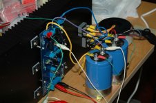
Tested one channel and the result is quite good on scope. Distortioin is 0.2% at 4.5W output. K170/J74 bias at 5.6mA using 22R source resistors. The matching of IRFP240/9240 is quite good also and current is from 0.48 to 0.49A and variation is within 2% for bias current.
Only waiting for the metal plates and support bar of the casing and then I can assembly the whole amp.
Only waiting for the metal plates and support bar of the casing and then I can assembly the whole amp.
Attachments

- Home
- Amplifiers
- Pass Labs
- F4 power amplifier