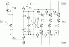
You are changing the resistors the wrong way - use 5K pot (P1) and 5K resistor (R9).
EDIT - 0.8V measures across source resistors is 1.7A -- that's a lot of bias current!! What are you trying to set? 0.3V is ideal.
EDIT - 0.8V measures across source resistors is 1.7A -- that's a lot of bias current!! What are you trying to set? 0.3V is ideal.
Last edited:
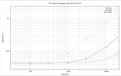
R9 at 5k and pot at ten K will give a very wide range hotter than 6L6 would call for ( more current) . More current produces much more heat and lower distortion so it is a trade off. 6L6 is correct start at .3 V and work your way hotter SLOWLY . 1.7a is a lot of heat needing larger heat sinks. The life of this with more than 1 amp can be called into question . Thanks for the graphs on a real unit. Very interesting the upper harmonic at 1watt stay flat at 50 volts very nice work.You are changing the resistors the wrong way - use 5K pot (P1) and 5K resistor (R9).
EDIT - 0.8V measures across source resistors is 1.7A -- that's a lot of bias current!! What are you trying to set? 0.3V is ideal.
Last edited:
You are changing the resistors the wrong way - use 5K pot (P1) and 5K resistor (R9).
EDIT - 0.8V measures across source resistors is 1.7A -- that's a lot of bias current!! What are you trying to set? 0.3V is ideal.
I did... but the bias is getting higher (1.XX V)....
Yes... I know 0.8V is too big...
1st change is parallelling 10K (to get 5K) on R9... Unfortunately bias is getting higher... After putting in series with 22K, I started to get a lower Bias... I'm settled on 22K and 10K. With those value I can set the bias around 0.2V...
But the question remains : Is it OK for me to use R9-22K and P1-10K..??? Or is there anything i should check...?? so far the heat is OK but still monitoring its stability
regards
Last edited:
lhquam. Granted that you still have operational/stereo F5, Teaser F6 and Teaser F6CC, and maybe an older generation 60W/ch receiver you covet.. Any one of them; if idle is a power preamplifier which will easily drive F4. Clearly this is a temporary fix, and one whereby you had fully characterized the unbeatable performance of the FW amps. I may sound/be absurd, but in the past year I have used a Threshold S/150 as a power preamplifier when I needed a 60Vp-p across the primary of a torroid power transformer.
Best regards
Best regards
lhquam. Granted that you still have operational/stereo F5, Teaser F6 and Teaser F6CC, and maybe an older generation 60W/ch receiver you covet.. Any one of them; if idle is a power preamplifier which will easily drive F4. Clearly this is a temporary fix, and one whereby you had fully characterized the unbeatable performance of the FW amps. I may sound/be absurd, but in the past year I have used a Threshold S/150 as a power preamplifier when I needed a 60Vp-p across the primary of a torroid power transformer.
Best regards
Yes, I have considered that and have discussed it with BuzzForb. One issue is that so preserve the sonic character of the (pre-)amplifier, its idle current and load must be similar to that for which it was designed. If the load resistance is increased on an amplifier with a common source output stage feedback then the amount of feedback increases similarly, changing the sonic character for better or worse depending on your point of view.
If you want a preamplifier with an F5 topology and feedback, some version of EUVL's F5X-preamplifier would be fine and would have reasonable power requirements.
I am currently looking at combining some of the ideas from the LSK-Pre thread http://www.diyaudio.com/forums/pass-labs/244106-lsk-pre-baf-2013-a-15.html#post3730923 with my Curllian-F4 design.
I am glad that you are pursuing many choices. A clear winner will emerge.Yes, I have considered that and have discussed it with BuzzForb. One issue is that so preserve the sonic character of the (pre-)amplifier, its idle current and load must be similar to that for which it was designed. If the load resistance is increased on an amplifier with a common source output stage feedback then the amount of feedback increases similarly, changing the sonic character for better or worse depending on your point of view.
If you want a preamplifier with an F5 topology and feedback, some version of EUVL's F5X-preamplifier would be fine and would have reasonable power requirements.
I am currently looking at combining some of the ideas from the LSK-Pre thread http://www.diyaudio.com/forums/pass-labs/244106-lsk-pre-baf-2013-a-15.html#post3730923 with my Curllian-F4 design.
How can there be a "clear winner" when in the end the decision is subjective.I am glad that you are pursuing many choices. A clear winner will emerge.
Wishful thinking on my part for you to assemble a preamp which will be accepted widely by DIYers. But; clearly a clear winner is the one which will be fully satisfactory to you.How can there be a "clear winner" when in the end the decision is subjective.
Hi,
I think I have often read about nacked/cripled/ even liberated F4, but a search just displays one of my own posts.
I know it is somewhere in here, but it would be tuff to read it all again.
The question: Am I right that to disable the input buffer in a standard F-4 I have to remove q1, Q2, R3 and R4, and short gate to drain in both channels ?
Thanks in advance
Arthur.
Also see post 3354 and following
ZM - thanks for the schematic - the picture is worth a1000+ words 😉
ZM - thanks for the schematic - the picture is worth a1000+ words 😉
One thing worth mentioning - with a crippled F4 it becomes very easy to increase the rail voltage for even lower distortion....
Look at BA-3 article - the Burning Amp complimentary output stage is almost exactily the same as F4, and higher rails show pure improvement.
Look at BA-3 article - the Burning Amp complimentary output stage is almost exactily the same as F4, and higher rails show pure improvement.
I am not sure that the 1K resistor R1 wants to be in series with the input. With the high MOSFET Ciss capacitances, R1 will roll off the high frequency response. Simulations show the following THD behavior with R1=10R, 100R, and 1K.
Attachments
Here is a minimal crippling of the F4. I have been using this for many months and it measures and listens fine. The simulations are also fine. The advantage of this version is that you can add a 3-pin header which provides either the In2 connection for the crippled F4, or a jumper for the uncrippled F4.
Attachments
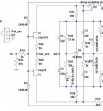
The 1K input resistor is to act as a gatestopper on the input Jfet buffer, to keep high-freq oscillation at bay.
As the input buffer isn't used on a crippled F4, it's not strictly necessary. The Mosfets have thier own gatestopper resistors.
As the input buffer isn't used on a crippled F4, it's not strictly necessary. The Mosfets have thier own gatestopper resistors.
mea culpa ; didn't checked pic I posted - just saw title of it (F4 crippled) prior to attaching it
that resistor need to be either zero or bridge or tiniest one , just as lhquam wrote
that resistor need to be either zero or bridge or tiniest one , just as lhquam wrote
Looking closer at the F4 liberated schematic I notice that we have 2 large electrolytics directly in the signal input.
That is a good thing because they block any DC from the preamp and that the preamp then does not need to have an output cap ?, and it is a bad thing because electrolytics tends to add to the sound, sometimes more when they are biased.
Is it wortwhile to bypass C1 and C2 with film caps ?
I think they have to be that large because of the low input impedance to the power mosfets, so filmcaps only would be huge.
- Home
- Amplifiers
- Pass Labs
- F4 power amplifier