if I wanted to increase the capacitance in the psu, from what's in the schematic, which is a CRC composed of
15,000uF x 2
0.47R x 4
15,000uF x 2
to say use 33,000uF x 2 would this be beneficial at all, and would the resistance value change as well?
15,000uF x 2
0.47R x 4
15,000uF x 2
to say use 33,000uF x 2 would this be beneficial at all, and would the resistance value change as well?
thanks for your help everyone! I am now lacking a single part for my build... namely the diodes. I did some digging around and found a tube full of some IR "drek" as someone around here might say... Further investigation showed them to be HFA06PB120, "leaded versions".
Datasheet:
http://www.vishay.com/docs/94037/94037hfa.pdf
now, the F4 schematic says 35A / 200V ... I'm assuming the 35A is the max repetitive forward current, and these are 24A each.... so, would that be 24A x 2 > 35A, so these are fine? I'm assuming the 200 is the anode voltage, and these are rated up to 1200v, so looks good. Assuming the times two thing is not just wishful thinking, perhaps these will work?
luvdunhill said:thanks for your help everyone! I am now lacking a single part for my build... namely the diodes. I did some digging around and found a tube full of some IR "drek" as someone around here might say... Further investigation showed them to be HFA06PB120, "leaded versions".
Datasheet:
http://www.vishay.com/docs/94037/94037hfa.pdf
now, the F4 schematic says 35A / 200V ... I'm assuming the 35A is the max repetitive forward current, and these are 24A each.... so, would that be 24A x 2 > 35A, so these are fine? I'm assuming the 200 is the anode voltage, and these are rated up to 1200v, so looks good. Assuming the times two thing is not just wishful thinking, perhaps these will work?
I even used the word "drek" and not even an off-topic reply?
luvdunhill said:
I even used the word "drek" and not even an off-topic reply?
may I .......... but later ....... (when I have time to find pdf and compare)
if nobody else ( worthier ) gives ya an answer .......

Ducky,
4 of those things can handle a total dissipation that is 10 times the power rating of the amp they're feeding.
The IR's forward voltage number is pretty steep, but no big deal as the customer is a push-pully client.
On the other hand, they're worthless, how about i'll do you a favor and take that diode load off your chest.
Hello
Can somebody tell me where is the post about of check point to F4?
Thank you very much
Jose
Can somebody tell me where is the post about of check point to F4?
Thank you very much
Jose
José Humberto said:Hello
Can somebody tell me where is the post about of check point to F4?
Thank you very much
Jose
Hi Jose,
maybe the following link, Post #1490:
http://www.diyaudio.com/forums/showthread.php?s=&threadid=97540&perpage=25&pagenumber=60
Best Regards,
a.
José Humberto said:Hello
Can somebody tell me where is the post about of check point to F4?
Thank you very much
Jose
also Notes from NP f4 Manual (version of 16-Jul-2007):
"Output device bias is approximately .43 amps per device, which measures 200mV across the .47 ohm source resistors.
All devices are matched for Vgs to .02V.
Cold, bias is adjusted low at 130 mV and readjusted as the amplifi er warms up.
The proper value is achieved after 1 hour with the heat sinks at about 50 deg C.
P2 is adjusted for minimal DC offset at output."
a.
José Humberto said:Hello
Can somebody tell me where is the post about of check point to F4?
Thank you very much
Jose
Also see my posts #2084 and #2085 here:
http://www.diyaudio.com/forums/showthread.php?s=&threadid=97540&perpage=25&pagenumber=84
a.
jacco vermeulen said:Ducky,
4 of those things can handle a total dissipation that is 10 times the power rating of the amp they're feeding.
The IR's forward voltage number is pretty steep, but no big deal as the customer is a push-pully client.
On the other hand, they're worthless, how about i'll do you a favor and take that diode load off your chest.
heh, why are they worthless? I didn't think about Vf, that's a good point.
I'm never going to turn down super-rare, super-awesome Jacco diodes... what do you recommend to use?
Cold, bias is adjusted low at 130 mV and readjusted as the amplifi er warms up.
The proper value is achieved after 1 hour with the heat sinks at about 50 deg C.
P2 is adjusted for minimal DC offset at output."
This also very much depends on the heatsink used... Mine 2 where about 1,5hour becomming thermal-stable....
Jesper.
luvdunhill said:recommend
Capman,
i'd save those monsters for a rainy day if you contemplate on building a huge power amp at a later stage.
Personally speaking, anything with a trr of somewhere around 100nS or less is fine in my book as long as they're the soft recovery type.
I often use stuff like Phily BY229 for little amps, but mainly cause i'm a cheapscate and buy such parts for less than current fetishista types cost.
Biased at 1.6A you'll need to heatsink TO220/TO247 rectifier diodes, easier and cheaper to stick a metal brick to the bottom of a chassis, your choice.
So, four F4 boards are now stuffed, except for the input JFETs. Looks like we need to match at 5mA current, so I'm guessing that BL grade makes sense for both type of parts? I was thinking of using a circuit like this to match:
this is more complicated that the circuit I've used in the past, which is:
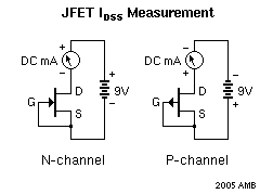
The first measures Vgs at 5mA the second matches based on Idss at saturation.
Which method would you recommend using? I got all the time in the world, as this sort of stuff is particularly relaxing for me 🙂
An externally hosted image should be here but it was not working when we last tested it.
this is more complicated that the circuit I've used in the past, which is:
The first measures Vgs at 5mA the second matches based on Idss at saturation.
Which method would you recommend using? I got all the time in the world, as this sort of stuff is particularly relaxing for me 🙂
jacco vermeulen said:Use Mr Boening's setup and match them at different current levels if you enjoy it so much.
well, I was thinking just matching at 5mA for all 'em. Not sure how to do it for the p-channel parts though... swap the top 9v polarity? now to check the parts bin to see how many I have 🙂
thanks so much!
Re: grounding
Why have you guys not come up with one Star ? Ths looks like two stars attached to each other. If you use the amp in stereo: Where would you connect the Grounds of the ouitput binding: to the first star (input signal or the second (PSU) ?
Actually I have my F4 made ready for testing and the grounding has been as well my last open question...
Andrzej Sochon said:Hello,
I would like to share grounding idea of my ballanced f4. Peter Daniel helped me, thank you very much, Peter, so I hope attached drawing will help some of novices too.
Wishing Nelson quick and full recovery,
Andrzej
Why have you guys not come up with one Star ? Ths looks like two stars attached to each other. If you use the amp in stereo: Where would you connect the Grounds of the ouitput binding: to the first star (input signal or the second (PSU) ?
Actually I have my F4 made ready for testing and the grounding has been as well my last open question...
No actual star ground meets the theoretical perfection as a
ground.
The 2 star or a hierarchical ground solves the problem of
high supply pulse currents going through a single ground whose
imperfection contaminates the signal grounds.
ground.
The 2 star or a hierarchical ground solves the problem of
high supply pulse currents going through a single ground whose
imperfection contaminates the signal grounds.
THX, it'S up and running...still on the testbench, but everything behaves well, currently it has 130mV over the 0.5 resistor (the caddocks I used were not available in 0.47)...let's see if it gets warmer after an hour or so, but I used quiet massive HEatsinks...so is a higher bias interesting if the heat sinks allow for that ?
- Home
- Amplifiers
- Pass Labs
- F4 power amplifier