frankly , have no idea how to simulate power of
that's the thing I didn't even think of
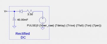
I also developed a simulation of my amplifier that shows a similar, but not identical behavior. The simulated power supplies are SPICE pulse voltage sources of the form:
PULSE({Vinitial} {Von} {Tdelay} {Trise} {Tfall} {Ton} {Tper})
In the simulation below, Tdelay=20sec, Ton=60sec, Tper=120sec. Trise and Tfall were 1.6mSec, and not important. The circuit contains a diode so that when AC power is shut off, the rail voltage decay will be determined by the current thru the circuit, not back into the transformer simulated by the voltage source. The 3.5R resistor was empirically from the measured behavior of my amplifier, shown in post #1408.
Attachments
@ Ian
it teaches us that we can trust in Papa's words , as long math is not involved
in other circumstances , his math is impeccable
it teaches us that we can trust in Papa's words , as long math is not involved
in other circumstances , his math is impeccable
I've not considered power off behaviour either, how serious an issue in practice do you think this is likely to be? If you have an amplifier already built then isn't it worth trying with a cheap loudspeaker?
Has there been any discussion of the shutdown circuit? I don't recall reading anything mentioning SCRs but I may have missed it.
When I turn off power to my amplifier, there is a very minor "click" in the speakers. Noticeable, but not in any way damaging to the speakers.
Does anyone know whether the production XA25 is totally free from power-on and power-off "thumps" or "clicks".
well , it is production
and I know that every PL/FW product you can use even with Lowthers
edit : I believe Denis can confirm my strong hunch/experience
and I know that every PL/FW product you can use even with Lowthers
edit : I believe Denis can confirm my strong hunch/experience
Some speculation:
If the XA25V2 sense resistors have been reduced in resistance that might allow the rail voltages to be reduced and the OS idle current to be increased for increased class-A wattage and no change in overall power dissipation.
If the XA25V2 sense resistors have been reduced in resistance that might allow the rail voltages to be reduced and the OS idle current to be increased for increased class-A wattage and no change in overall power dissipation.
I do not understand how changing the cascode base voltage would significantly affect the current thru the cascode transistor. If there were resistors from the cascode emitters to a reference voltage, such as ground, it might work.
I tried it with the opto's disconncted and the bias is at 4.6 amps and with opto's bias is at 2.4 amps.
I was using 0.4 ohm sense resistors above but I meant to use 0.5 ohm resistors to get a 2 amp bias current. With 0.5 resistors it shows 1.97 amps.


It looks like it's changing the output bias by changing the resistance of cascode transistors.
I don't think so. Changing the voltage at the base of the cascode transistors will not significantly alter the current through them. The input JFETs will see a different voltage at the cascode emitters but this does not change their behaviour much since they are effectively a current source into the cascode voltage source.
- Home
- Amplifiers
- Pass Labs
- F4 Beast Builders