FE bias sanity check
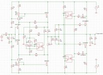
People (aka greedy boys) have spent a lot of effort to stabilize the front-end (FE) mosfet bias current. Here are actual measurements of an amplifier I have built with the topology shown below. As you can see, there is no servo (or thermistors) in the FE of that amplifier.
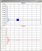
From a cold start I made three voltage measurements and a heatsink temperature measurement at 9 points in time, spanning just over one hour.
Across positive rail Rsen (0R27)
Across positive rail J313 source resistor (22R1)
Output offset voltage.
The OS and FE bias currents were computed from the voltages.
Conclusion: No need for a servo to stabilize the FE bias vs. temperature.
People (aka greedy boys) have spent a lot of effort to stabilize the front-end (FE) mosfet bias current. Here are actual measurements of an amplifier I have built with the topology shown below. As you can see, there is no servo (or thermistors) in the FE of that amplifier.
From a cold start I made three voltage measurements and a heatsink temperature measurement at 9 points in time, spanning just over one hour.
Across positive rail Rsen (0R27)
Across positive rail J313 source resistor (22R1)
Output offset voltage.
The OS and FE bias currents were computed from the voltages.
Conclusion: No need for a servo to stabilize the FE bias vs. temperature.
Attachments

agree with you 100%
I did what I did from several reasons ...... first we always are figuring how exactly Papa did it , further how to make it different
not necessary better (possible or not ) , but necessary not (much or at all ) worse than Papa's original
well , that I can say for my self for sure
long time past the point of must have new amp ......... never going to past the point of must have fun
(Italics written in Homer Simpson voice)
🙂
Last edited:
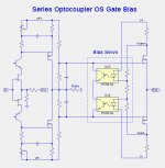
People (aka greedy boys) have spent a lot of effort to stabilize the front-end (FE) mosfet bias current. Here are actual measurements of an amplifier I have built with the topology shown below.
Conclusion: No need for a servo to stabilize the FE bias vs. temperature.
Agreed, did anyone previously disagree? This really is no different to the regular PL front end albeit with capacitor bypass, i.e. it has DC local feedback due to the MOSFET source resistors. The need for a servo, if there is one, would arise only if you wish to remove the MOSFET source resistor and the associated capacitor.
agree with you 100%
long time past the point of must have new amp ......... never going to past the point of must have fun
(Italics written in Homer Simpson voice)
🙂
so true
but never going past the point of understanding for me...it's still a learning process...but still fun...
so, sorry for the naive questions...I am aware that you guys have been at this thread for a long time, and also aware of the effort put in.....
ok creep mode over
you had all legitimate questions
🙂
to be precise - all questions are legitimate ; only in case when asked by someone demanding spoonfed , they become questionable

🙂
to be precise - all questions are legitimate ; only in case when asked by someone demanding spoonfed , they become questionable
Hi everyone,
I'm following this thread with great interest and I'm gathering parts to build the "beast". For now I have the hockey pucks and I'm looking for a transformer, but I don't know what voltage to choose for secondary. Any recommendation?
Lynn, in post #1290 you had positive results with stability of OS. The rails are 40V. Do you recommend to try that OS bias method? I'm thinking of mixing Sony VFET PII FE with OS from post #1290. Any thoughts?
Thanks.
Ian:
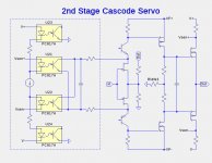
Here is a topology without DC degeneration of the j313/K2013 MOSFETs. I found resistor parameters that work well.
Interesting twist using an opto LED (U23) as a ‘diode’ matching the voltage drop of the bias opto (U21) 🙂 I’ve not tried this but I did do something similar using an LM385 voltage reference. In my case I used it just on the FE but I wasn’t happy with the amount of servo gain, i.e. it didn’t control the FE MOSFET current very tightly. Does your variant work better taking the sense from the output stage MOSFETs?
More importantly, does completely eliminating the degeneration resistors and associated capacitors in this way actually improve performance of the amplifier?
what is max. value [mA] you can take as passed?
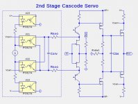
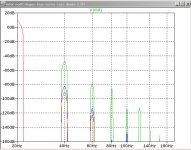
I am seeing additional problems with both the DC degenerated and undegenerated j313/k2013 versions of the servo circuit. At power-up, the capacitors in the circuit, particularly between the OS FET gates (Cbs), and between the opto output transistor emitters and collectors (Csrv) are initially discharged. The plot below shows plots of the currents thru the output FETs and the j313/k2013 vs. time for different values of the Csrv. In LTSpice the easiest way to view the power-up behavior is by using the "startup" option of the ".trans" command:
.tran 0 {tstop} {tstart} {sdur} startup
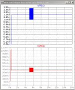
For small values of Csrv and low frequencies, there is a significant amount of (distorted) signal is fed back thru the cascode emitter connection. The spectral plots shows this behavior with Rsvo=4K7 and Csrv having values 1pf, 33uF, and 100uf.
For large values of Csrv (> 33uF) the startup currents gete quite large.
The best values I have found are Csrv=33uF Rsvo=4K7.
- The first current plots are with Csrv=1pF. The J313 current briefly spikes to over 100mA.
- The second current plots are with Csrv=33uF, and shows high currents for both J313 and the OS NFET.
- The spectral plot is for 1W, 20Hz, and 8R load with Csrv = 1pF (green), 33uF (blue), and 100uF (red).
Attachments
Last edited:
struggle with same test (signal present during startup procedure ) ate at least 3 months of my simulating time
another reason for Papa's (no lesser than hysterical) amusement 🙂
so , thsi drek iteration of mine , with CM , is immune to that too ....... no excessive DC or currents anywhere
another reason for Papa's (no lesser than hysterical) amusement 🙂
so , thsi drek iteration of mine , with CM , is immune to that too ....... no excessive DC or currents anywhere
Last edited:
so , conclusion .... on the screen , Babelfish XA25 is waaay better than Papa's original
(possibility that some Beast from the Dark will jump and bite me during prototyping , is strong as Force )

(possibility that some Beast from the Dark will jump and bite me during prototyping , is strong as Force )
So perhaps separate servos are the way to go rather than wrap one around two amplifier stages? Here is another variation of that concept that I have been playing around with.
Then again, maybe it is better to avoid the FE servo altogether. Decisions, decisions...
Then again, maybe it is better to avoid the FE servo altogether. Decisions, decisions...
Attachments
Ian: It looks like C1 presents the same problem with being initially discharged and causing high currents in the FE at power-up.
I've not investigated that phenomenon in any detail but you may well be correct. Will this not be the case with any servo operating across these points, i.e. startup needs to establish a higher current than the steady state in order to activate the opto and hence the bias control?
Perhaps ZM's is a better approach?
Perhaps ZM's is a better approach?
why Boucherot on output ?
I noticed that the PL XA25 uses one so I thought I would experiment to see what effect it has. Definitely not saying it must be there.
- Home
- Amplifiers
- Pass Labs
- F4 Beast Builders