I found a couple of errors in my previous tests. One of the issues with connecting the servo output to the 2nd stage gates is the voltage range encountered across the opto transistors.
I am having difficulty getting that circuit to perform well for rail voltage and temperature variations and also keeping the opto transistor voltage below 36V. There is a PC817x opto series from Sharp that handles 80V max across the transistors, so the voltage range might not really be an issue.
I am having difficulty getting that circuit to perform well for rail voltage and temperature variations and also keeping the opto transistor voltage below 36V. There is a PC817x opto series from Sharp that handles 80V max across the transistors, so the voltage range might not really be an issue.
"This aside, what is your thinking in including source resistors in the 2nd stage MOSFETs, albeit bypassed by the capacitor? Given that this stage is included in the servo loop, it should be perfectly fine (and simpler) to omit both the resistors and capacitors."
I when I find a parameter set where the voltage across those caps is near zero, I will try to set the resistors to near zero and run simulations.
I am currently running simulations of just that. It does look promising.
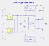
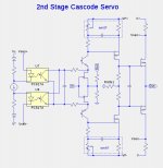
Here are concept schematics with Rldfe, a resistor load on the FE that controls open-loop gain. Also shown are open-loop gain plots for Rldfe at 1k 10k and 100k, in a simulation of the 2nd stage cascode servo.
Here are concept schematics with Rldfe, a resistor load on the FE that controls open-loop gain. Also shown are open-loop gain plots for Rldfe at 1k 10k and 100k, in a simulation of the 2nd stage cascode servo.
Attachments
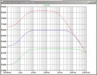
You are seeing 86 dB of gain open loop with 100k FE loading? Interesting as my figure is closer to 64 dB. Maybe down to our choice of resistors elsewhere?
input JFet loading, what else
Well it actually depends on JFET loading together with the value of the source resistor to ground...
isn't the goal of the game getting rid of them , in all stages ?
either removing them completely (what I did) , or nulling them with strategic placed caps?
OK , there is one , which we can rid of in OLG simulation (if needed) - feedback resistor from input JFet sources to gnd
either removing them completely (what I did) , or nulling them with strategic placed caps?
OK , there is one , which we can rid of in OLG simulation (if needed) - feedback resistor from input JFet sources to gnd
Last edited:
Yes, but I have no idea how to get rid of the resistor connecting the two input JFET sources to ground. I've suggested before that it is not possible to remove all degeneration and, so far at least, nobody has said otherwise. The circuit simply doesn't work if this resistor is removed. Are you saying you managed it somehow?
Maybe there is some confusion due to not referring to a circuit diagram? I'm talking about R5 in your post (#1314).
yup , we are thinking about same resistor and we agree that , if we want ( and must) to have feedback , there it is
if one want to remove it for testing purpose , all you need is to short it , what else ?
though , extra precise sim of OLG condition is tiresome , at least in my case with optos in drains , because there is no mechanism of maintaining 0 offset when cutting feedback net
then need to replace optos with voltage sources , etc.
wasn't so enthusiastic , better to play dumb
🙂
yup , we are thinking about same resistor and we agree that , if we want ( and must) to have feedback , there it is
if one want to remove it for testing purpose , all you need is to short it , what else ?
🙂
Ah, shorting rather than removing - now I understand 🙂 Apologies.
Agree that shorting means that we must either operate the amplifier with no global feedback at all or 100%. Probably neither is particularly desirable.

A couple of naive questions if I may as I'm trying to fiddle with this in spice on 24v rails. I've tried to use the fairchild fets on the front end but can't get the bias voltage high enough, and I cant find the spice models for the toshiba fets.
Has anybody got the toshiba models they are willing to share?.
Are these spice models closely guarded, I ask because I posted a request a while back for any details on the hockey puck models but go no response.
I'm trying with 24v because I have a number of 24v 5a smps supplies which I'd like to try. I was going to try them with an F6 because I had trouble with wandering bias a few years back. My mains wanders between 242 and 254v and I thought the smps might be a solution. I'm also in the middle of a project to try them with a latfet mofo...they've got to be used
- Home
- Amplifiers
- Pass Labs
- F4 Beast Builders