frankly , I was lost just looking at newest iteration pics , so didn't invest more time in deciphering
btw, nothing wrong with servo-less FE (as is shown to us Greedy Boyz more than once)....... I did it just because I wanted
catch22 is still in OS , and it will stay there .....
catch22 is still in OS , and it will stay there .....
frankly , I was lost just looking at newest iteration pics , so didn't invest more time in deciphering
Too much of the shutdown circuit is hidden behind the ribbon cable. I haven't figured out the role of the two 220uF electrolytics that might be connected pos-to-pos.
btw, nothing wrong with servo-less FE (as is shown to us Greedy Boyz more than once)....... I did it just because I wanted
No harm in that 🙂
My interest in a servo FE is to eliminate the degeneration resistor altogether and more importantly, the associated capacitor bypass so that we get no low frequency roll off. Your variation looks interesting and I suspect has a nice, slow startup characteristic as the opto output transistor bypass caps charge up.
One question though, given that you have eliminated the pots, how do you adjust the DC offset?
self centering , due to overall feedback net
single (sole) trimpot is ditto to precise CCS chip , for CM biasing , and it is there (of course) for OS Iq biasing
single (sole) trimpot is ditto to precise CCS chip , for CM biasing , and it is there (of course) for OS Iq biasing
.....I suspect has a nice, slow startup characteristic as the opto output transistor bypass caps charge up.......
yup , startup , regarding voltages and currents in FE , is slow and nice , but not because of optos ...... charge of caps in drains (parallel to optos) is limited with JFets Idss and opto bjt isn't even conducting until caps are charged(enough)
credit ...... not certainly mine
solution is result of utter and shameless thievery

That is what I meant regarding startup. Apologies if I didn't make myself clear.
My experience with self centering of output voltage is not so good but could be due to lower global feedback in my case.
My experience with self centering of output voltage is not so good but could be due to lower global feedback in my case.
ZD25 power-up power-down waveforms
Today I made some measurements of my ZD25, which is similar to the XA25. The measurements were:
Today I made some measurements of my ZD25, which is similar to the XA25. The measurements were:
- CH1 (yellow): VF+
- CH4 Violet: Drive+
- CH2 Cyan: Drive-
- CH3 Pink: Vout
- CH4-CH2 Blue: Drive+ - Drive-
- Complete power-up and power-down sequence at 5 secs/div
- Power-up pulse at 0.5 secs/div
- Power-down pulse at 1 secs/div.
Attachments


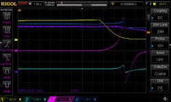
The start-up pulses shown in my previous post will not cause a speaker thump because the output FETs do not start conducting until about 13 seconds after power is applied, when VF+ (the yellow trace) declines about 6V.
This behavior must be considered when evaluating the servo designs.
This behavior must be considered when evaluating the servo designs.
However, the power-off pulses will hit the speaker, unless the SCR in the shutdown circuit is triggered in some manner. It does not happen with my shutdown circuit.
I've not considered power off behaviour either, how serious an issue in practice do you think this is likely to be? If you have an amplifier already built then isn't it worth trying with a cheap loudspeaker?
Has there been any discussion of the shutdown circuit? I don't recall reading anything mentioning SCRs but I may have missed it.
Has there been any discussion of the shutdown circuit? I don't recall reading anything mentioning SCRs but I may have missed it.
SCR used in overhystericoutputcurrent protection
10A I believe , though - Papa relaxed triggering somewhat in latest amp iteration, according to his words
I have a feeling that , if amp is not making trouble during startup , it'll behave when sent to sleep ....... I mean - at least this one
10A I believe , though - Papa relaxed triggering somewhat in latest amp iteration, according to his words
I have a feeling that , if amp is not making trouble during startup , it'll behave when sent to sleep ....... I mean - at least this one
"overhystericoutputcurrent"? Not sure what you mean.
You know that SCR is used or is this speculation? I see that Pass Labs documentation says that the amp shuts down when 10A output current is exceeded but it doesn't elaborate.
You know that SCR is used or is this speculation? I see that Pass Labs documentation says that the amp shuts down when 10A output current is exceeded but it doesn't elaborate.
I'm confused.
What do we actually know about this shutdown mechanism? For example, does it limit the current to 10A, shutdown but reset automatically, shutdown requiring a manual restart or something else? Useful to understand the function before trying to analyse the mechanism. Again, not saying we need this in our own amplifiers, more a matter of interest.
What do we actually know about this shutdown mechanism? For example, does it limit the current to 10A, shutdown but reset automatically, shutdown requiring a manual restart or something else? Useful to understand the function before trying to analyse the mechanism. Again, not saying we need this in our own amplifiers, more a matter of interest.
I believe info is in user manual
manual reset - shut off , power up
ZM dumb for that , so no investing enormous brain power in
manual reset - shut off , power up
ZM dumb for that , so no investing enormous brain power in
Last edited:
My apologies, you are correct:
"it will protect itself by shutting off any channel which outputs more than 10 amps (200 watts peak into 2 ohms). The protection circuit is reset by turning the amp off for a few moments and then turning it back on."
Teach me to skim rather than read properly!
"it will protect itself by shutting off any channel which outputs more than 10 amps (200 watts peak into 2 ohms). The protection circuit is reset by turning the amp off for a few moments and then turning it back on."
Teach me to skim rather than read properly!
well , it's written somewhere , just cant remember where exactly
edit - you posted while I was doing other things 🙂
edit - you posted while I was doing other things 🙂
Last edited:
- Home
- Amplifiers
- Pass Labs
- F4 Beast Builders