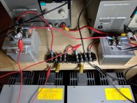
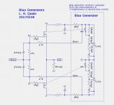
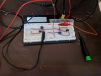
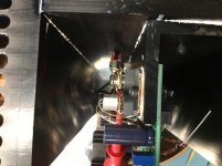
Here is the OPS wired up for business. Just resistors and two capacitors. The circuit is what L. H Quam posted except I did not use TL431 for this test.
Since the hockey pucks use ring terminals, I pulled out some terminal blocks to allow wiring up the circuit quickly.
The capacitors are necessary. Without them, the 47k resistors kill the input signal.
Since the hockey pucks use ring terminals, I pulled out some terminal blocks to allow wiring up the circuit quickly.
The capacitors are necessary. Without them, the 47k resistors kill the input signal.
Attachments
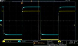
I too noticed an artifact on the bottom corner of the square wave this one done at about 200KHz bias around 2Amps (Wish I had better test equipment like yours!).jpg")
What bias current are you using?
Keep up the good work!
What bias current are you using?
Keep up the good work!
I too noticed an artifact on the bottom corner of the square wave this one done at about 200KHz bias around 2Amps (Wish I had better test equipment like yours!)View attachment 660713
What bias current are you using?
Keep up the good work!
Bias 600 mA to 2A. I adjust the bias up and down to see if there is any difference. Since the load is 47 ohms, I am not using very much of the 0A to 200A capability. When I have a large capacitor on the hockey pucks, I will do a one-cycle sine wave at 200A.
Looking in the datasheets and measuring the hockey pucks, I do not see that the metal slug that contacts the heatsink is attached in any way to drain, source or gate.
Is this correct?
Is this correct?
Yes so it makes mounting easier just apply goop and bolt down. 🙂
That is great news. Thanks for the reply.
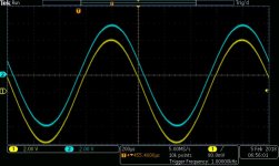
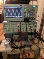
Here is the OPS running with the new bias circuit. Scope shot of 1kHz sine wave.
At 6V Vds, the N-channel FET is not happy. The top half of the sine wave is visibly pushed to the right. The cure was to increase the positive power supply to 12V. The negative supply was left at 6V to experiment. At 12V Vds for the N-channel FET, the sine wave is no longer pushed to the right.
This may be a visible manifestation of the device capacitance being voltage dependent.
The N FET appears to have lots more low voltage capacitance than the P FET.
Next I will measure Vgs at temperatures from cold to hot to select temp comp resistors.
Attachments
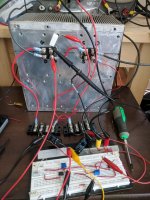
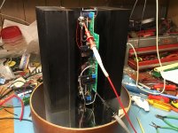
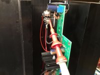
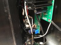
Modified the bias circuit to implement the offset correction resistors and pot that are in the F4. It works great. Here are the beastie MOSFETs on a equally beastie heatsink.
The bias is set for 1.1 amps. Output offset voltage is tweakable to below 1mV.
It is a beautiful and elegant bias circuit.
DIY Store F4 boards will be in-hand soon to commit this lashup to a more permanent arrangement.
The bias is set for 1.1 amps. Output offset voltage is tweakable to below 1mV.
It is a beautiful and elegant bias circuit.
DIY Store F4 boards will be in-hand soon to commit this lashup to a more permanent arrangement.
Attachments
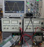
Frequency response of the naked OPS.
-3dB around 100 kHz
Output disappears around 1Mhz
At 2.2 Mhz, the output is visibly rising off of zero.
Output climbs visibly from 2.2MHz until resonance is hit at 13MHz. The output is going crazy at 13 MHz.
The resonance after 13 MHz falls with increasing freq.
My sig gen runs out of gas at 30MHz.
-3dB around 100 kHz
Output disappears around 1Mhz
At 2.2 Mhz, the output is visibly rising off of zero.
Output climbs visibly from 2.2MHz until resonance is hit at 13MHz. The output is going crazy at 13 MHz.
The resonance after 13 MHz falls with increasing freq.
My sig gen runs out of gas at 30MHz.
Can you share the " Elegant Bias circuit"? From the photo it does indeed look elegant as there are very few components.
I note no temp compensation NTC's or anything, now you really have my interest. 🙂
I note no temp compensation NTC's or anything, now you really have my interest. 🙂
Can you share the " Elegant Bias circuit"? From the photo it does indeed look elegant as there are very few components.
I note no temp compensation NTC's or anything, now you really have my interest. 🙂
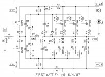
I just lifted the output bias string from the F4 r0 schematic. P1 sets the bias and P2 adjusts the output offset.
I used two of the TL431 but I will be dropping back to one TL431 when the F4 PCBs from the DIY Audio Store arrive.
The first time through adjusting the pots, I set the current for 1.1A cold. When warm, the bias was beyond 3A. While the heatsink was still hot, I adjusted for 1.1A. After the heatsink cooled off, the bias is 0.7A.
I bought some thermistor NTCs and will eventually add one to the TL431 circuit with associated resistors. I think adding the thermistor is advisable. If the heatsink gets hot enough, the bias current rises precipitously.
Attachments
Nelson showed in one of his last BAF talks the Ciss and Crss curves of certain pucks that fell down to some hundred pico farad already at 25V with the Crss.
You can see this types at the picture of the 6moons XA25 review.
Also it seems better to go higher with the rail voltage to more than 30V nevertheless.
The types you use have fairly high capacitances and are harder to drive.
You can see this types at the picture of the 6moons XA25 review.
Also it seems better to go higher with the rail voltage to more than 30V nevertheless.
The types you use have fairly high capacitances and are harder to drive.
Nelson showed in one of his last BAF talks the Ciss and Crss curves of certain pucks that fell down to some hundred pico farad already at 25V with the Crss.
You can see this types at the picture of the 6moons XA25 review.
Also it seems better to go higher with the rail voltage to more than 30V nevertheless.
The types you use have fairly high capacitances and are harder to drive.
Hi Generg
Thank you for the suggestions. I did see this problem with 6V rails. When I increased from 6V to 12V the outputs became much easier to drive. It is apparent that the capacitance is much worse at lower voltage rails.
I cannot run more than 30V for my particular application. My goal is to be able to take the hockey pucks to full output current. The parts I am using have 200A maximum for external connections per the datasheet. When I have my F4 running with these pucks, I will be posting 200A one-cycle sine wave captures.
For this application, I plan to keep the hockey puck rails at + / - 12V and the bias+input circuit at + / - 24v.
The application will not be an 8 ohm speaker. It will be a sub-ohm ribbon tweeter. I will test at 20 milliohms load and then maybe at 10 milliohms. That is why I chose the hockey pucks with lowest Rdson.
Here is the first channel on the bench. This build is based on teabags AL boards. Just a few tweaks and it is easily converted from VFETs to pucks.
And the porn for Zenmod...
Now I just need to build the second channel.
And the porn for Zenmod...
Now I just need to build the second channel.
Attachments
- Home
- Amplifiers
- Pass Labs
- F4 Beast Builders