you'll certainly having bigger Cojones than Mighty ZM !!

I wouldn't dare to even power them up , without proper servo bias ..........
OK - will power them up , but wouldn't dare to connect speakers
I wouldn't dare to even power them up , without proper servo bias ..........
OK - will power them up , but wouldn't dare to connect speakers
Here is the first channel on the bench. This build is based on teabags AL boards. Just a few tweaks and it is easily converted from VFETs to pucks.
And the porn for Zenmod...
Now I just need to build the second channel.
Elegant how the thermistor screws into the puck.
Can you post the schematic with your final tweaks?
better to wait a month , to try it in vivo
abandoned current mirror + precise CCS approach , going to indra's Voodoo Hall chips**
going to make a killer
**ordered , waiting
abandoned current mirror + precise CCS approach , going to indra's Voodoo Hall chips**
going to make a killer
**ordered , waiting
** killer chips.....
:--))
At least Nelson must have a reason to go in his XA25 down to 0.166 Ohm instead of goldies....
so the Voodo Hall chips with near to zero could be a step more forward indeed.
It is such pleasure to have you alle here....
🙂🙂🙂🙂
:--))
At least Nelson must have a reason to go in his XA25 down to 0.166 Ohm instead of goldies....
so the Voodo Hall chips with near to zero could be a step more forward indeed.
It is such pleasure to have you alle here....
🙂🙂🙂🙂
and we are proud to be part of Alle
frankly , rare occasion for me , feeling as part of Alle , and not having bad taste in stomach

frankly , rare occasion for me , feeling as part of Alle , and not having bad taste in stomach
better to wait a month , to try it in vivo
abandoned current mirror + precise CCS approach , going to indra's Voodoo Hall chips**
going to make a killer
**ordered , waiting
Why not temp compensation as per the attached?
Attachments
because I'm not making it to have it , but to make it as best/craziest I can
Understood. Looking forward to your results. These pucking FETs are tolerant to stupid mistakes. I have been pleasantly surprised that I have not turned one into a fuse.
I successfully built mine without any sissy control circuitry.
I then added a thermistor in the bias circuitry just for fun. Brother Generg convinced me to try it.
Either way there is no issue. I have reasonably over engineered heatsinking though.
I then added a thermistor in the bias circuitry just for fun. Brother Generg convinced me to try it.
Either way there is no issue. I have reasonably over engineered heatsinking though.

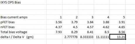
I thought I would share some measurements to show how bias current vs total Vgs works for my pair of hockey pucks.
I set up the normal test for Vgs by strapping gate to drain and then forcing a current through the OPS pair.
This will help when I set bias using the TL431 adjustment pot.
I set up the normal test for Vgs by strapping gate to drain and then forcing a current through the OPS pair.
This will help when I set bias using the TL431 adjustment pot.
Attachments
Very interesting results. I had noted in a previous post in this thread that when I had taken my hockey pucks up to a bias of 6A or more the sound changed and the bass became more defined. I think even Nelson made similar comments about the the more bias the better only if your heatsinking and power supply was up to the task. Thank you for taking the time to share your testing but I'm still looking forward to your 200Amp test though!
Very interesting results. I had noted in a previous post in this thread that when I had taken my hockey pucks up to a bias of 6A or more the sound changed and the bass became more defined. I think even Nelson made similar comments about the the more bias the better only if your heatsinking and power supply was up to the task. Thank you for taking the time to share your testing but I'm still looking forward to your 200Amp test though!
The pucks definitely have lots more gm at higher bias. If that translates into better sound of some sort, then you could measure the parts before the build and set the bias for the gm desired.
The parts for my initial F4 board are on the way. I did not realize that the TL431 on the F4 board is a TO92. The BOM on the web site is silent as to package type. At the moment, I only have 8-pin dip parts.
I also am looking forward to making a 200A sine wave. I have it from a reliable source that the Ixys datasheets are very conservative and a number that quantifies how conservative. As a result, once I make a 200A sine wave, I will also try for 300A and 400A.
No sense in having a canon if you can't fire off a round.
On a mildly more serious note, I don't suppose you've investigated vgs/temp at a particular bias level?
200 Amp, are you driving ribbons with a 5 volt supply?
should work quite well with a good unity gain stable op amp driving high bias ( 5 amp) output transistors in a non switching config. Vgs swing must exceed power rails by 6 ish volts for full current peaks.
supply droop will be more then a minor annoyance.
A Weller Trigger soldering gun fed with a 100w SS or tube amp will allow you to test the theory. Drive the ribbon off the soldering tip connections with AT LEAST 6 guage wire.
Last edited:
On a mildly more serious note, I don't suppose you've investigated vgs/temp at a particular bias level?
Yes I investigated. Mother nature made me do it.
The first heatsinks I used are CPU coolers that require a fan. The hockey pucks' bias current runs away when the they get hot.
I took the prevailing advice and bought a large, heavy heatsink. This heatsink is a much more satisfying experience. As a practical observation, having run this heatsink to very warm, set the cold bias to 1/2 of what you want at operating temperature and then get the heastsink warm with a sig gen and a load, and then adjust the final bias.
The problem is that if the ambient temperature of your listening room varies widely, the operating bias will probably be different at different room temperatures. I would recommend a torture test to be safe. For my intended ribbon tweeter use, I am not worried about destroying the ribbon if the amplifier causes a problem. I just install a new ribbon and continue.
- Home
- Amplifiers
- Pass Labs
- F4 Beast Builders