Do you see any increase in noise at the output as a result of adding your gm adjustment? I find that adding even a small resistance, e.g. 10R in series with the input increases noise from just less than 1uv to 10uv.
Are your noise measurements from SPICE? Again perspective is important. 10uV into an 8R load is 6.25pW (6.25e-12)
SPICE yes, so all the usual caveats apply. That said, and although I accept your point about perspective, the increase in noise is still x10 even for a resistor <10R. If the resistor is increased sufficiently to equalise the AC current in the output FETS, the noise becomes worse still (~ x100 over the no resistor case). This may or may not be important in practice but I would prefer not to add noise at all and hence and I am wondering if there may be better way to achieve the same effect. Unfortunately so far I haven't found any that don't have their own issues.
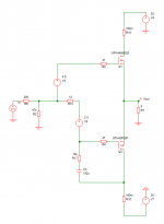
Lynn: have you considered this alternative for gm adjustment? it has its own pros and cons of course but does allow a smaller resistor in series with the input which benefits both noise and damping factor. The downside is reduced rejection of noise on the negative supply.
Attachments
The other downside is that the drain of the OS FET has a very high K2 component, thus changing the harmonic character of the signal to the gate. I would need to run simulations to determine how significant that effect would be and also the PSRR issue that you suggest.
My simulations suggest that the THD is lower with this configuration but I'm always happy to have it confirmed (or disproved).
Lower than what? Lower than without any adjustment of the PMOS FET gm, or lower than using my gm adjustment circuit?My simulations suggest that the THD is lower with this configuration but I'm always happy to have it confirmed (or disproved).
Good. I will do some simulations to look at the PSRR issues.The latter.
I have not yet run any simulations on that circuit, but after closer examination it looks like the R17 C17 combination could connect to ground with the same effect, and C17 could probably be eliminated. Something looks very "fishy" here. Why would 10K to ground at that point make any significant difference to the gm of the PFET?Lynn: have you considered this alternative for gm adjustment? it has its own pros and cons of course but does allow a smaller resistor in series with the input which benefits both noise and damping factor. The downside is reduced rejection of noise on the negative supply.
You may be right. I hoped to achieve some measure of negative feedback from the connection to the PFET drain but it seems that it is negligible and connecting to ground has a very similar effect. I can't explain why a 10k resistor to ground would have the desired amount of attenuation though so perhaps something is indeed fishy as you put it. Interestingly, both forms of connection appear to result in both an increase in NFET signal current and a decrease in PFET (dc values are unchanged) which is not what I expected. Further investigation is required.
Is that a Kairos speaker in your avatar?
Sorry for the late reply.. somehow my thread subscription was not turned on.
ScanSpeak 2way i build long time ago. I don't have these anymore.
Im currently working on the F4 beast pcb design. I will show some stuff in a few weeks probably. Im going to try the opto bias parallel version.
Martin
...
Im currently working on the F4 beast pcb design. I will show some stuff in a few weeks probably. Im going to try the opto bias parallel version.
Martin
I recently did bench tests of the opto bias parallel version and have found some issues bias adjustment procedure. That circuit has a positive temperature coefficient, meaning that the bias current increases with heatsink, optocoupler, and zener diode temperature. In my build the bias current increases about 4mA/C of heatsink temperature. That is not necessarily bad, but it does increase the time before the heqatsink temperature stabilizes, and makes it difficult to guess the initial adjustment of the bias current. I can provide more details as needed.
Is there a substantial benefit in using the Cbias capacitors?
Referring to the schematic in post #1594, there might be three options regarding Cbias (C1 and C2):
- Cbias as shown in post #1594, connected between top of R10 and J313 source pin. FET has only DC source degeneration. Gain is insensitive to pot adjustment.
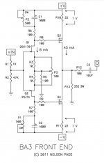
- Cbias connected between top of R10 and rail (VF+). This is the same as in the BA3 Front End, shown below. FET has full source degeneration. Gain is insensitive to pot adjustment and about 15dB lower than option 1.
- No Cbias. FET has full source degeneration. The open-loop gain is sensitive to the pot adjustment. Poor choice.
Attachments
There is also a fourth option: Cbias connected across R8 (Rs). FET has only DC source degeneration. Gain is sensitive to pot adjustment. Probably not a great choice but worth noting for completeness.
There is also a fourth option: Cbias connected across R8 (Rs). FET has only DC source degeneration. Gain is sensitive to pot adjustment. Probably not a great choice but worth noting for completeness.
You are correct. I actually tried that option about 1 year ago. The main problems I saw were with the RC time constant and with the series resistance of the capacitor, and variability between that resistance between the caps on the positive and negative rails. In order to get a time constant equal to option 1 requires the capacitor to be about 5 times larger.
If you were to use that fourth option, you would also probably want to have the capacitor of option 2 so that pot adjustment does not change the gain and thus the even harmonics. If the cap series resistance is not a problem, that should result in essentially the same behavior as option 1.
Last edited:
Hi,
Noob questions:
1. Does the output stage with parallel opto bias have any voltage gain?
2. How much voltage swing does the output stage require from front end?
I want to try a tube front end with ECC88.
Noob questions:
1. Does the output stage with parallel opto bias have any voltage gain?
2. How much voltage swing does the output stage require from front end?
I want to try a tube front end with ECC88.
1. no
2.rail to rail , at least
be careful which iteration of OS you are going to use - some of them are more and some are less stable regarding stability of output offset , counting on NFB to take care of same
2.rail to rail , at least
be careful which iteration of OS you are going to use - some of them are more and some are less stable regarding stability of output offset , counting on NFB to take care of same
1. no
2.rail to rail , at least
be careful which iteration of OS you are going to use - some of them are more and some are less stable regarding stability of output offset , counting on NFB to take care of same
Thank you for clarification Zen Mod.
Does anyone have any recommendation on tube front end? I was looking at a ECC88 SRPP, similar to the one attached.

- Home
- Amplifiers
- Pass Labs
- F4 Beast Builders