
Figuring out a BOM and have questions on C1, C8, C10.
I'm planning on using the outboard PCB for 15 1000uf caps for C1. Which means the 1uf C8 on the backside of the board is not populated, correct?
What about C10- 220uf on the schematic? Not populated and covered by my C1 caps? Thanks.
Yes, you are right. If you use the 15x 1000uF caps of higher quality to replace C1, the bypass caps C8 and C10 are not used.
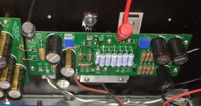
Powered up the right channel board yesterday and all went well. I will make a couple small updates to the boards (correct a silk screen mistake and add 2nd resistor location for R5 to make it easier to parallel resistors to create the desired resistance to match a particular Q1).
Hi Chas
Adding a second resistor location is brilliant but I can’t find it on my PCBs.
Was it implemented?
If it was please tell me the name of the second resistor besides the obvious R3, R4.
Thanks
Eric
The changes required to make space for the additional resistor were significant enough that I would have wanted to do a second test build to reverify the boards, and I was not up for that. I solved the issue by soldering two resistors directly together to create the value I needed. Both parallel and series are easy to do this way.
Test Points
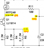
I don't think I mentioned it, but there are test points on the amp boards that correspond the locations on the Firstwatt schematic with indicated voltages. There are two holes at each test point to solder in a "U" shaped lead for easy clip attachment when making adjustments to the board. Most are located at the top of the board for easy access.
I don't think I mentioned it, but there are test points on the amp boards that correspond the locations on the Firstwatt schematic with indicated voltages. There are two holes at each test point to solder in a "U" shaped lead for easy clip attachment when making adjustments to the board. Most are located at the top of the board for easy access.
Attachments
received my boards, thank you for all the effort and wonderful boards ! excited to make this amp!
Hi Chas,
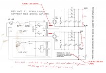
PSU schemathics seems the same as 2X24VDC for F1/F1J: as 46DC are needed, I think that it is necessary to put secondaries in series (not one for channel) or to have a donut with 2X36VAC secondaries....
PSU schemathics seems the same as 2X24VDC for F1/F1J: as 46DC are needed, I think that it is necessary to put secondaries in series (not one for channel) or to have a donut with 2X36VAC secondaries....
Thanks for pointing that out, I missed updating the AC voltage into the rectifiers.
Attachments
Last edited:

Thanks Chas
Is 400VA enough?
Maybe for all our technical questions we should now simply do a search or refer to the present F3 building thread.
F3 Builders Thread
Thanks
Eric
Last edited:
PCBs landed safely in my island! Fantastic boards and supersafe package!


Many many thanks, Chas! : cheers:
Many many thanks, Chas! : cheers:
Nice big order.
The PCBs on the left side are for a different project? I don’t recognized the PCBs.
Looking forward to seeing your build.
BR
Eric
The PCBs on the left side are for a different project? I don’t recognized the PCBs.
Looking forward to seeing your build.
BR
Eric
- Home
- Group Buys
- F3 Clone Board Set Group Buy