Well, there's also Epcos, Vishay, Kemet ... if you shop around a bit and are not in a hurry, you can find some amazing bargains, as these are now standard industrial items on power electronics like industrial SMPS or power inverters.
I paid 38 EUR for two boxes with 27 caps each of these, surplus ...
I've built the B+ power supply for my EL84PP tube amp by paralleling a few of this type of caps for each channel ...
I got the same boxes for the same price from ebay.de 🙂
I'm about to finish my F3 and have taken the advice that Chas provided about adjusting R5 using a 10ohm 10w variable pot to get 3.5v from the LU1014. Is there any reason that I need to remove the pot from the amp once it is set? I know that I would need to secure the pot.
I built up the amp, and put a 10ohm 5W potentiometer in place of R5 with the initial resistance set per Vgs and the chart below. P1 and P2 set to mid position by counting turns. After approximately 5 minutes after power up begin to periodically adjust P1 and the "R5" potentiometer as the amp warms up to keep the voltages at Q1 drain and R9-C1 junction at the values on the F3 schematic (3.5V and 21V respectively). Let the amp run for 1 hour make final adjustments. Remove "R5" potentiometer and measure resistance. Solder in real resistor for R5 of closest value I could make up from resistors on hand.
Just a pair of questions, Chas: did you add the pot with the 1 Ohm resistor in parallel? could you pkease link a proper 5W potentiometer? Thanks

I plan on using Simic ll caps on the output board. Mouser is out of 35v and 50v are a bit pricey would 25volt suffice? Thanks for your help. Mark
@Peppennino,
This is the 5w pot listed for R5 adjustments:
026TB32R100B1A1 CTS Electronic Components | Mouser
This is the 5w pot listed for R5 adjustments:
026TB32R100B1A1 CTS Electronic Components | Mouser
One more question. my Jfet’s are 1.069, would you recommend 2.7 ohm or 2.0 plus 0.47 ?panasonic Erx choices seem slim. Thanks again
I’m getting closer to finishing my F3. One channel is operational and the second one is in place a wired. I just need to fire it up and adjust it. The 10ohm pot works very well, and I’m not sure if I will remove it. My only concern is that it is just being held in place with the wires. I would want to secure it better if I leave it in.
That’s great news BRN!
What size chassis are you building your F3 in? Looking forward to some pictures 😉
What size chassis are you building your F3 in? Looking forward to some pictures 😉
I’m using the 4U 400 Disspante chassis for the build. I used this chassis for another amp that I pulled the amps out of. It’s dual mono using 2 project16 CRC power supplies with two 50uF motor run caps on each supply.
Looking forward to getting it done and listening to it.
Once I get this done I can get back to the AD1862 DAC to figure out why it is not working. I have to focus on one project at a time.
Looking forward to getting it done and listening to it.
Once I get this done I can get back to the AD1862 DAC to figure out why it is not working. I have to focus on one project at a time.
@Peppennino,
This is the 5w pot listed for R5 adjustments:
026TB32R100B1A1 CTS Electronic Components | Mouser
Ops, didn't read the note on BOM! thanks, Vunce!

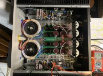
I finally finished my F3. I left the pots in. I did not see a reason to remove them. It took the right channel awhile to settle and get 3.5v. I only did a quick listen on some inexpensive speakers in my work space, but the amp sounded very good. I was feeding the amp from a TB DAC and ACA+ pre. The Test points make measuring so much easier. These are great boards.
Attachments
Looks good BRN, did everything align well with the LU1014 adapter and the hole placement on the board? By the measurements it should, but I never got to check this first hand.
Congratulations BRN!
You’ve got a lot of goodies packed neatly in that chassis, savvy thinking in how you supported the trimpots 😉 nice job.
Enjoy!!
You’ve got a lot of goodies packed neatly in that chassis, savvy thinking in how you supported the trimpots 😉 nice job.
Enjoy!!
Chas,
The holes worked perfectly. The pins on the adapter boards are a little tight, but fit. I was actually dry fitting the boards and had one of them reversed and the mounting holes did not align. It was then that I realized the LU1014 holes on the board were different, so that they would accommodate the adapter boards. Great job on them.
Vince,
I initially used wire (20 gauge solid core) to hold the pots in place, but that is not secure. I used some standoffs from the bottom plate and zip ties to secure them, so now they are nice and stable.
Hello all. I have a set of F3 boards from Chas on their way and Nautibuoy very kindly furnished me with some LU1014s.
I read hear more than once that the F3 may not be particularly well suited to 'conventional' speakers with a crossover. And I note the low damping factor, although I have no idea what influence the DF has to the sound of an amp.
Could someone please elaborate a bit on this, and ultimately would I be wasting my time and money building the F3 for my 2 ways and 2.5 ways.? I would need to invest in the meaty psu/ output caps and heatsinking even just for testing purposes. Maybe I could use some.48v SMPS to test.
Cheers!
Here are the suggestions for speakers from the F3 manual:
I am building a set of Troels Faital 3WC 12" which I think will be a very good match. The F3 also sounded great in a biamp setup on my 3 way speakers driving the mid and tweeter - it did not do well driving the whole speaker which has approximately 2 ohm minimum impedance it was clipping at a very modest volume.
This doesn't answer all of your questions, hopefully others can fill in more from their experience.
The F3 has enough damping factor (8) to work well with loudspeakers that mate
well with tube amplifiers in general, and it delivers good performance into 4 and 16
ohms also – see the distortion curves at the back of this manual. It is designed
around relatively high efficiency speakers and it particularly shines with those that
have 90 dB/watt sensitivity or greater, but you can hook it up to anything you like,
as long as you adjust your expectations as to how loud it will play.
I am building a set of Troels Faital 3WC 12" which I think will be a very good match. The F3 also sounded great in a biamp setup on my 3 way speakers driving the mid and tweeter - it did not do well driving the whole speaker which has approximately 2 ohm minimum impedance it was clipping at a very modest volume.
This doesn't answer all of your questions, hopefully others can fill in more from their experience.
- Home
- Amplifiers
- Pass Labs
- F3 Builders Thread